Temperature Sensor: Difference between revisions
| Line 18: | Line 18: | ||
<math> | <math> | ||
u(\lambda, T) = \frac{{8 \pi c}}{{\lambda^5 | u(\lambda, T) = \frac{{8 \pi c}}{{\lambda^5 ( e^{\frac{{hc}}{{\lambda k_B T}}} - 1 )}} | ||
</math> | </math> | ||
Revision as of 20:42, 27 April 2024
Team members
Duan Xitong, Hu Anqi, Ge Weifang
Introduction
This project aims to design and fabricate a non-contact infrared thermometer based on the MLX90614 infrared temperature sensor. A non-contact infrared thermometer is a device that can measure the surface temperature of an object without direct contacting the object.
In experiments with electronic devices and circuit boards, the temperature of circuit components is an important indicator, and excessive temperatures may affect the performance of the circuit or even damage the circuit components. Therefore, monitoring the temperature of circuit components is quite essential to ensure the stable operation of device and extend the lifespan of circuit components.
One simple and direct way to detect whether a circuit component is abnormally hot is to touch it directly with hands. However, if the temperature is too high, such as above 70°C, direct hand contact for a few seconds can result in burns. Hence, we aim to design and fabricate a temperature detection device based on an infrared temperature sensor to ensure the safety of operators.
Compared to traditional temperature detection methods, this infrared thermometer does not require direct contact with the object, thereby avoiding any impact on the object being measured. This feature makes it suitable for a wide range of applications in industrial and medical fields.
Principle
The MLX90614 infrared temperature sensor is a non-contact infrared temperature sensor that can be used to measure the surface temperature of a target object. It can transmit continuously the measured object temperature for an object temperature range of -20 to 120 ̊C with an output resolution of 0.14 ̊C. The working principle is based on infrared radiation temperature measurement technology.
Thermal Radiation Properties
According to Planck's radiation law, all objects emit electromagnetic radiation at certain frequencies and intensities, including visible light and infrared radiation. According to Stefan-Boltzmann law, the radiant power of an object is proportional to the fourth power of its absolute temperature. Therefore, we can calculate the surface temperature of an object by detecting the intensity of the emitted infrared radiation, which can be described as this equation:
Infrared Detection and Temperature Calculation
The MLX90614 is built from 2 chips developed and manufactured by Melexis:
(1)The Infra Red thermopile detector MLX81101.
When infrared radiation enters the detectors, they generate weak electrical signals proportional to the received infrared radiation intensity.
(2)The signal conditioning ASSP MLX90302, specially designed to process the output of IR sensor.
The MLX90302 includes a low noise amplifier, high resolution 17-bit ADC and powerful DSP unit, for handling the electrical signals received from the infrared detector and calculating the surface temperature of the target object. The calculated object and ambient temperatures are available in RAM of MLX90302 with resolution of 0.01 ̊C. They are accessible by 2 wire serial SMBus compatible protocol (0.02°C resolution) or via 10-bit PWM (Pulse Width Modulated) output of the device. [1]
Experimental components and setup
Components:
1. Thermopile: MLX90614 Infrared Temperature Sensor
2. SSD1306 OLED Screen
3. Arduino board:
(1) ATMEGA328 Arduino Pro Mini USD 3.72 (+ TTL to USB)
(2) Mini USB nano V3.0 CH340G 5V Arduino board
(3) Cytron Maker uno+ Arduino
4. GH0781RA2C Laser Diode/Red LED (λ650nm)
5. Battery (9V)/power supply
6. Other components: 1x open switch button, 20x jumper wires and 1x solderless breadboard.
Experimental setup:

Taking Arduino pro mini as an example, the experimental setup is mainly composed of the following parts:
Arduino board is responsible for running the code and connecting other components, Thermopile sensor (MLX90614) for temperature detection, and OLED screen (SSD1306) displays the temperature reading in real time.
In addition, USB to TTL is to connect the computer and Arduino board to upload the code. The λ650nm red LED helps us visually locate the direction and position of temperature detection, and the 9V battery ensures that the detection setup can carry out on-site testing.
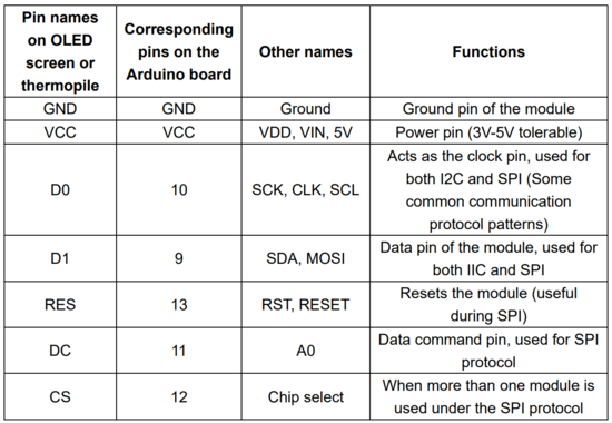
For OLED screen, Thermopile, the names pins and corresponding functions are shown in Figure 3 [2]:

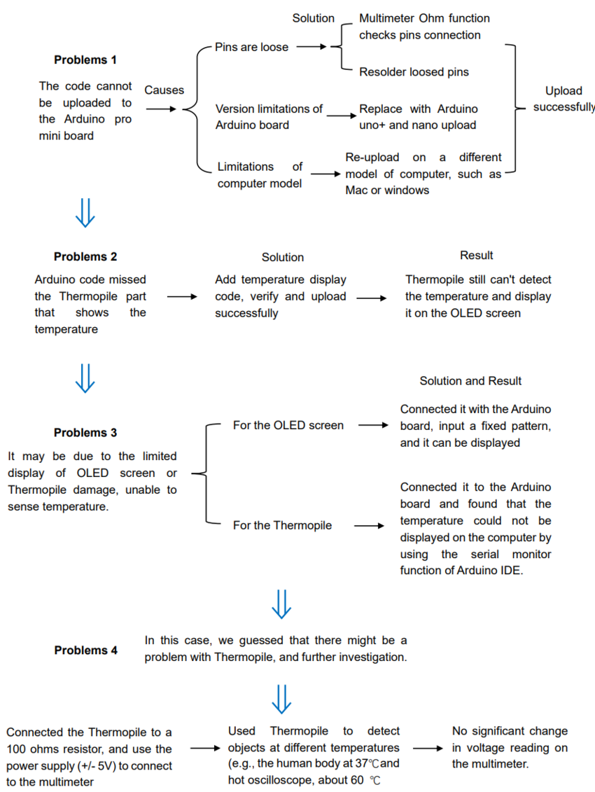
Results and debug analysis
Unfortunately, we didn't get the temperature measurement in real time on the OLED screen.
In view of the problems, we have carried out the following analysis:

Reference
- ↑ Melexis. "MLX90614 Digital Plug & Play Infrared Thermometer in TO-Can." https://www.melexis.com/en/product/MLX90614/Digital-Plug-Play-Infrared-Thermometer-TO-Can.
- ↑ CIRCUIT DIGEST, "Interfacing SSD1306 OLED Display with Arduino", https://webbook.nist.gov/cgi/cbook.cgi?ID=C7732185&Type=IR-SPEC&Index=0#IR-SPEC.
