Temperature Sensor
Team members
Duan Xitong, Hu Anqi, Ge Weifang
Introdution
Experimental components and setup
Components:
1. Thermopile: MLX90614 Infrared Temperature Sensor
2.SSD1306 OLED Screen
3. Arduino board:
(1) ATMEGA328 Arduino Pro Mini USD 3.72 (+ TTL to USB)
(2)Mini USB nano V3.0 CH340G 5V Arduino board
(3)Cytron Maker uno+ Arduino
4. GH0781RA2C Laser Diode/Red LED (λ650nm)
5. Battery (9V)/power supply
6. Other components: 1x open switch button, 20x jumper wires and 1x solderless breadboard.
Experimental setup:

Taking Arduino pro mini as an example, the experimental setup is mainly composed of the following parts:
Arduino board is responsible for running the code and connecting other components, Thermopile sensor (MLX90614) for temperature detection, and OLED screen (SSD1306) displays the temperature reading in real time.
In addition, USB to TTL is to connect the computer and Arduino board to upload the code. The λ650nm red LED helps us visually locate the direction and position of temperature detection, and the 9V battery ensures that the detection setup can carry out on-site testing.
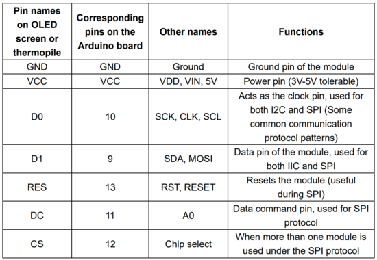
For OLED screen, Thermopile, the names pins and corresponding functions are shown in Figure 3:

Results and debug analysis
Unfortunately, we didn't get the temperature measurement in real time on the OLED screen.
In view of the problems, we have carried out the following analysis: