Optical Sensor for UV Radiation
Team members
LiJiasheng, ChenXingjian, LiXuejian
Introduction
Ultraviolet (UV) radiation, a fundamental component of sunlight, is critically influential in numerous environmental and biological processes. These processes range from the synthesis of Vitamin D in humans to the degradation of materials exposed to outdoor environments. Monitoring UV radiation is not only essential for assessing its ecological impacts but also for various practical applications including weather forecasting, climate monitoring, and public health advisories against UV overexposure.
Given the significance of accurately measuring UV radiation, the development of reliable and precise UV sensors is of paramount importance. The optical sensor designed in this project utilizes the S5971 photodiode from Hamamatsu, known for its high sensitivity and low noise characteristics, making it an excellent choice for precision light measurements.
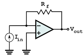
The primary objective of this experiment is to develop an optical sensor that can accurately measure the UV component of sunlight. The S5971 photodiode, although highly sensitive, produces only minimal photocurrent under indoor lighting conditions, necessitating the use of a Transimpedance Amplifier (TIA) circuit to convert this small current into a measurable voltage.The designed sensor system integrates the S5971 photodiode with a TIA circuit to amplify the weak signals produced when exposed to light sources. By measuring the voltage across the resistor in the TIA circuit, the amplified voltage corresponding to the intensity of incident light can be determined. This setup allows for the derivation of a quantitative relationship between light intensity and output voltage.
To specifically measure UV light intensity, the sensor system is tested under various conditions: with direct white light (representing broad-spectrum sunlight) and white light passed through a UV-pass filter. By comparing these measurements, the proportion of UV light in natural sunlight can be inferred, providing valuable data for environmental and health-related applications.
This project not only aims to develop a functional UV light sensor but also to enhance understanding of UV radiation's variability with daily and seasonal changes in sunlight exposure. This knowledge is crucial for applications ranging from solar power generation to environmental science studies and public health initiatives.
Principle of Reverse Biasing in Photodiodes
1.Enhanced Sensitivity and Stability
Reverse Biasing: In a reverse-biased setup, the photodiode is connected such that the anode is connected to a more negative voltage relative to the cathode. This configuration widens the depletion zone of the diode, which is the region devoid of charge carriers (electrons and holes).
Depletion Zone Expansion: The expansion of the depletion zone reduces the capacitance of the diode, allowing faster response times to changes in light intensity. A larger depletion zone can also improve the sensitivity of the photodiode by increasing the volume in which light-induced electron-hole pairs are generated.
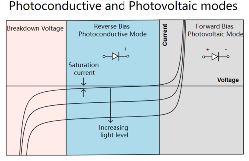
- Figure 1.Principle of Reverse Biasing in Photodiodes
2.Stable Current Response
Linear Response to Light: Under reverse bias, the photocurrent (current produced when the diode is exposed to light) is more stable and linear in relation to the light intensity. This stability is due to the minimization of recombination of electron-hole pairs within the depletion zone, meaning more of these pairs contribute to the current.
Low Dark Current: Reverse biasing also minimizes the dark current (the small current that flows through the photodiode even in the absence of light) which is essential for accurate light measurement. Dark current is primarily due to thermally generated carriers that are swept across the junction by the reverse bias; the higher the reverse voltage, the lower the dark current, up to a certain limit beyond which the diode may break down.
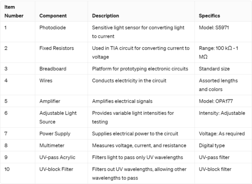
Equipment Needed
Experimental Set-up
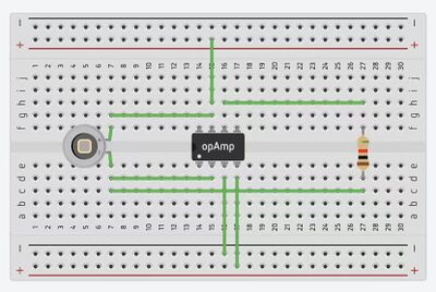
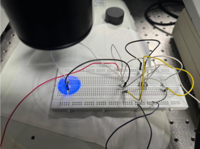
To set up the UV intensity measurement experiment using the S5971 photodiode, begin by assembling the circuit on a standard-sized breadboard.
- Figure 2.Breadboard schematic of the circuit.
Connect the S5971 photodiode and the OPA177 amplifier, using wires to complete the connections. Install a series of fixed resistors ranging from 100 kΩ to 1 MΩ between the amplifier's output and the ground to adjust the Transimpedance Amplifier (TIA) gain based on the expected light intensity.
- Figure 3.TIA circuit.
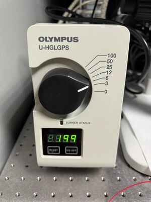
Position an adjustable light source so that it directly illuminates the photodiode, and use the UV-pass acrylic filter to isolate UV wavelengths for specific measurements, and replace it with the UV-block filter for measuring other wavelengths.
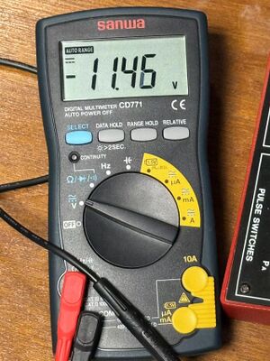
- Figure 4.The multimeter. Figure 5.The UV source.
Connect the power supply to the breadboard to power the circuit, and use a multimeter set to voltage measurement mode to read the output from the amplifier circuit, which is proportional to the light intensity hitting the photodiode.
