Temperature and humidity sensors: Difference between revisions
| (120 intermediate revisions by the same user not shown) | |||
| Line 6: | Line 6: | ||
== Objective == | == Objective == | ||
<b>(1)</b> Design and implement a real-time temperature and humidity monitoring system based on Arduino and the DHT11 sensor, capable of continuously acquiring environmental temperature and humidity data. The system is designed to fulfill the following functions: | |||
* Real-time Data Acquisition: Accurately measures the current ambient temperature and humidity. | * Real-time Data Acquisition: Accurately measures the current ambient temperature and humidity. | ||
* Dynamic Data Display: Continuously updates the | * Dynamic Data Display: Continuously updates the computer screen to reflect the latest measurement data. | ||
* Low Cost and High Scalability: Suitable for various applications such as smart home systems, agriculture, and warehouse environments, with potential extensions to wireless data transmission and other advanced functionalities. | * Low Cost and High Scalability: Suitable for various applications such as smart home systems, agriculture, and warehouse environments, with potential extensions to wireless data transmission and other advanced functionalities. | ||
<b>(2)</b> Compare the Performance of DHT11 and SHT31 Sensors in Different Environments: By simultaneously using the DHT11 and SHT31 sensors, compare the temperature and humidity data measured in both indoor and outdoor environments. Analyze the differences in measurement accuracy, stability, and response time between the two sensors. | |||
<b>(3)</b> Explore the Practical Application and Performance of the DHT11 Sensor: Focus on studying the performance of the DHT11 sensor in dynamically changing environments, particularly under conditions where temperature and humidity fluctuate significantly, and evaluate its suitability and reliability for practical applications. | |||
<b>(4)</b> Optimize Sensor Selection and Application Scenarios: Based on the experimental results, identify the strengths and limitations of both DHT11 and SHT31 sensors, helping to choose the most appropriate sensor for different scenarios. This is particularly relevant for projects where cost is a factor, or where high precision is not the primary concern, and how to efficiently use the DHT11. | |||
== Theory == | == Theory == | ||
=== Temperature Measurement === | |||
==== Definition of Temperature ==== | |||
Temperature is a fundamental physical quantity used to characterize the thermal state of a system, determining the direction of heat flow between two bodies. It is typically measured in degrees Celsius (°C), Kelvin (K), or Fahrenheit (°F), depending on the context. In the field of temperature measurement, various devices, including thermocouples, thermistors, and pyrometers, are used to determine temperature across different ranges. | Temperature is a fundamental physical quantity used to characterize the thermal state of a system, determining the direction of heat flow between two bodies. It is typically measured in degrees Celsius (°C), Kelvin (K), or Fahrenheit (°F), depending on the context. In the field of temperature measurement, various devices, including thermocouples, thermistors, and pyrometers, are used to determine temperature across different ranges. | ||
| Line 20: | Line 26: | ||
In the context of thermistors, temperature is directly related to resistance through a thermoresistive effect. Specifically, NTC (Negative Temperature Coefficient) thermistors show a decrease in resistance with an increase in temperature, making them useful for temperature measurement and control in electronics, industrial processes, and other applications requiring precision temperature data. | In the context of thermistors, temperature is directly related to resistance through a thermoresistive effect. Specifically, NTC (Negative Temperature Coefficient) thermistors show a decrease in resistance with an increase in temperature, making them useful for temperature measurement and control in electronics, industrial processes, and other applications requiring precision temperature data. | ||
==== NTC Thermistors ==== | |||
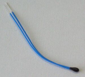
NTC (negative temperature coefficient) thermistor is a semiconductor device whose resistance value decreases with increasing temperature. This property is mainly due to the conductive mechanism of the semiconductor material: when the temperature increases, the electrons inside the semiconductor gain more energy and jump into the conduction band, increasing the number of free carriers, which reduces the resistance of the material. | |||
<center>[[File:NTC_bead.jpg|300px]]</center> | |||
<center>'''NTC thermistor bead structure'''</center> | |||
The relationship between temperature T (in Kelvin) and resistance R is often described by the Steinhart-Hart equation, which is widely used to model the behavior of thermistors: | |||
<center><span style="font-size:150%;"><math>R(T) = R_0 \exp\left[B \left( \frac{1}{T} - \frac{1}{T_0} \right)\right]</math></span></center> | |||
The absoute temperature then can be obtained by inverting the equation above: | |||
<center><span style="font-size:150%;"><math>T = \left( \frac{1}{T_0} + \frac{1}{B} \ln \frac{R}{R_0} \right)^{-1}</math></span></center> | |||
Where R0 is the resistance at a reference temperature T0 ,B is the material constant of the thermistor, T is the temperature of interest. | Where R0 is the resistance at a reference temperature T0 ,B is the material constant of the thermistor, T is the temperature of interest. | ||
[[File:ResistancevsTemperature.png| | |||
<center>[[File:ResistancevsTemperature.png|500px]]</center> | |||
<center> '''Resistance vs Temperature Curve</center>''' | |||
Figure 1 Resistance vs. Temperature Curve for 10 kΩ NTC Thermistor at 25°C | Figure 1 Resistance vs. Temperature Curve for 10 kΩ NTC Thermistor at 25°C | ||
| Line 33: | Line 50: | ||
NTC Thermistors exhibit a negative temperature coefficient (NTC), meaning their resistance decreases with an increase in temperature. They are used in various applications such as temperature measurement and compensation in electronics. These thermistors are particularly useful in electronics, air conditioning, and automotive applications due to their high sensitivity and low cost. | NTC Thermistors exhibit a negative temperature coefficient (NTC), meaning their resistance decreases with an increase in temperature. They are used in various applications such as temperature measurement and compensation in electronics. These thermistors are particularly useful in electronics, air conditioning, and automotive applications due to their high sensitivity and low cost. | ||
=== Humidity Measurement === | |||
==== Relative Humidity ==== | |||
Relative Humidity (R.H.) is one of the most commonly measured parameters in humidity measurement and plays a critical role in various industrial and commercial applications. It is defined as the ratio of the partial pressure of water vapor in the air (Pw) to the saturation vapor pressure (Ps) at a specific temperature, expressed as a percentage: | Relative Humidity (R.H.) is one of the most commonly measured parameters in humidity measurement and plays a critical role in various industrial and commercial applications. It is defined as the ratio of the partial pressure of water vapor in the air (Pw) to the saturation vapor pressure (Ps) at a specific temperature, expressed as a percentage: | ||
<center><span style="font-size:150%;"><math>\mathrm{R.H.} = \frac{P_w}{P_s} \times 100\%</math></span></center> | |||
Where Pw is the actual water vapor pressure in the air, and Ps is the saturation vapor pressure at the ambient temperature. "When temperature and pressure change, the corresponding water vapor pressure also changes, so the relative humidity will change as well. Relative humidity provides a measure of how much water vapor is present in the air relative to the maximum amount of water vapor the air can hold at a given temperature. | Where Pw is the actual water vapor pressure in the air, and Ps is the saturation vapor pressure at the ambient temperature. "When temperature and pressure change, the corresponding water vapor pressure also changes, so the relative humidity will change as well. Relative humidity provides a measure of how much water vapor is present in the air relative to the maximum amount of water vapor the air can hold at a given temperature. | ||
==== Resistive Humidity Sensors ==== | |||
Resistive humidity sensors operate based on changes in the conductivity of the sensor material as it absorbs water vapor. The resistance of the sensor decreases as the humidity increases, which is the primary transduction mechanism. These sensors typically utilize materials with significant changes in conductivity in response to moisture content, making them suitable for a variety of humidity sensing applications. | Resistive humidity sensors operate based on changes in the conductivity of the sensor material as it absorbs water vapor. The resistance of the sensor decreases as the humidity increases, which is the primary transduction mechanism. These sensors typically utilize materials with significant changes in conductivity in response to moisture content, making them suitable for a variety of humidity sensing applications. | ||
== Equipment Required == | == Equipment Required == | ||
=== DHT11 === | |||
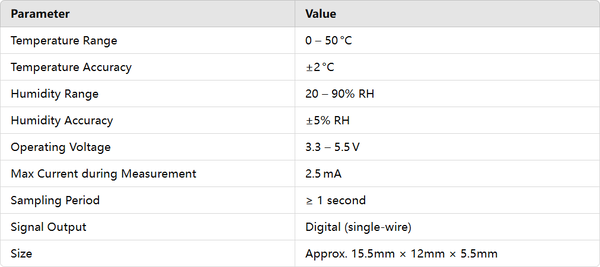
DHT11 is a temperature and humidity composite sensor with calibrated digital signal output, suitable for the measurement of ambient temperature and humidity. It adopts special digital module acquisition technology, which can provide high reliability and long-term stability, and is widely used in environmental monitoring, industrial control, home automation and other fields. | DHT11 is a temperature and humidity composite sensor with calibrated digital signal output, suitable for the measurement of ambient temperature and humidity. It adopts special digital module acquisition technology, which can provide high reliability and long-term stability, and is widely used in environmental monitoring, industrial control, home automation and other fields. | ||
==== Basic Features and Specifications ==== | |||
<center>[[File:【71】Picture 1.png|600px]]</center> | |||
<center>'''Basic Features and Specifications'''</center> | |||
==== Internal structure of the DHT11 sensor ==== | |||
DHT11 mainly consists of the following three parts: | |||
<b>(1)</b>Resistive moisture sensing element: used to measure air humidity. | |||
<b>(2)</b>NTC (negative temperature coefficient thermistor) temperature measuring element: used to measure the ambient temperature. | |||
<b>(3)</b>Internal microcontroller: used for data processing, calibration and communication. | |||
During the measurement process, the DHT11 sensor converts the temperature and humidity data into a standard digital signal through an internal signal conditioning circuit and transmits the data through a Single Wire protocol. | |||
==== Working principle ==== | |||
<b>(1)</b> Temperature Sensing: Use an NTC thermistor whose resistance varies with temperature. The onboard microcontroller converts this change into a calibrated digital signal. | |||
<b>(2)</b> Humidity Sensing: A capacitive or resistive humidity sensing element detects the moisture content in the air by measuring changes in electrical resistance or capacitance caused by water vapor. The onboard microcontroller then converts these changes into a humidity percentage. | |||
==== Pin specification ==== | |||
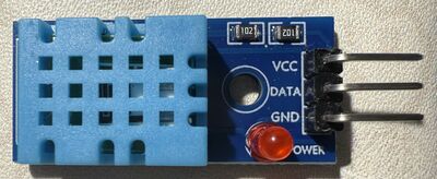
<center>[[File:DHT11.jpg|400px]]</center> | |||
<center>[[File:【71】Picture 3.png|600px]]</center> | |||
<center>'''Pin specification'''</center> | |||
==== Protocol and Data Format ==== | |||
The DHT11 uses a single-wire protocol to communicate with a microcontroller. After the microcontroller sends a start signal, the DHT11 switches from low-power mode to high-speed mode. It waits for the start signal to finish and then sends a response signal, followed by a data transmission. | |||
A complete data transmission consists of 40 bits, sent in order from the most significant bit to the least significant bit. | |||
Data format: | |||
• 8 bits: Humidity integer | |||
• 8 bits: Humidity decimal | |||
• 8 bits: Temperature integer | |||
• 8 bits: Temperature decimal | |||
• 8 bits: Checksum | |||
Totaling 5 bytes (40 bits). | |||
Since the resolution only ensures whole numbers, the decimal parts are always 0. | |||
The checksum is the sum of the first four bytes. The purpose of the checksum is to ensure accurate data transmission. | |||
The DHT11 only performs temperature and humidity measurements once it receives a start signal from the host. | |||
If no start signal is received, the DHT11 will not automatically perform measurements. | |||
After the data collection is complete and transmission ends, the DHT11 automatically switches back to low-speed mode. | |||
==== Operation Timing ==== | |||
<center>[[File:【71】Picture 4.jpg|600px]]</center> | |||
<center>'''Operation Timing'''</center> | |||
<b>(1)</b> Host Sends Initialization Signal | |||
The initialization process of the DHT11 is divided into the initialization signal and the response signal. | |||
First, the host pulls the data line low for at least 18 ms, then pulls it high again and waits for 20–40 μs (typically 30 μs). At this point, the initialization signal has been completely sent. | |||
<center>[[File:【71】Picture 5.jpg|600px]]</center> | |||
<center>'''Host Sends Initialization Signal'''</center> | |||
In slave mode, once the DHT11 receives the start signal, it triggers a temperature and humidity acquisition. If the start signal from the host is not received, the DHT11 will not actively perform temperature and humidity acquisition. After data collection, it switches to low-speed mode. | |||
<b>(2)</b> DHT11 Sends Response Signal | |||
After detecting the start signal, the DHT11 triggers a sampling process, pulls the data line low for 80 μs to indicate a response signal, and notifies the host that the data is ready. Then it pulls the line high for another 80 μs before beginning to transmit data. If the response signal detected is high level instead, the DHT11 initialization has failed—please check if the wiring is correct. | |||
Once the initialization signal is completely sent, if a low level is detected on the bus, start counting every 1 μs until the bus goes high, measuring the low-level time. After the bus is pulled high, start counting again to detect the following 80 μs high-level period. If this 80 μs high level is detected after the response signal, data reception is about to begin. | |||
In practice, the DHT11's response time may not be exactly 80 μs and often fluctuates. Generally, if the response occurs within 20–100 μs, it can be considered successful. | |||
<b>(3)</b> Data Transmission | |||
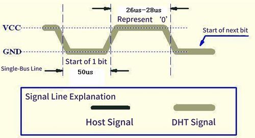
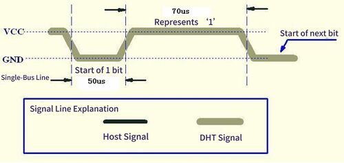
After pulling the data line high for 80 μs, the DHT11 begins transmitting data. Each bit of data starts with a 50 μs low-level signal, indicating to the host that a bit is about to be sent. The length of the following high-level signal determines whether the bit is a ‘0’ or a ‘1’. If the data line is pulled high after the 50 μs low level: | |||
• A high level lasting 26–28 μs indicates a “0” | |||
• A high level lasting 70 μs indicates a “1” | |||
After the last (40th) bit is transmitted, the DHT11 pulls the line low for 50 μs, indicating the end of data transmission. Then, the bus is pulled high by the pull-up resistor, entering an idle state. | |||
<center> | |||
{| style="margin: auto;" | |||
|- | |||
| <center>[[File:【71】Picture 6.jpg|500px]]</center> | |||
| <center>[[File:【71】Picture 7.jpg|500px]]</center> | |||
|- | |||
| <center>'''The representation of a logic ‘0’ signal'''</center> | |||
| <center>'''The representation of a logic ‘1’ signal'''</center> | |||
|} | |||
</center> | |||
==== Analysis of advantages and disadvantages ==== | |||
<b>(1)</b> Advantages | |||
• Calibrated digital output, easy to use | |||
• Ultra-low power consumption | |||
• Long communication distance, simple interface | |||
• Very low cost, suitable for mass deployment | |||
<b>(2)</b> Disadvantages | |||
• Temperature error ±2 °C, humidity error ±5% RH | |||
• Minimum sampling interval ≥ 1 s, not suitable for high-speed acquisition | |||
• Certain limitations on usage environment | |||
• Not suitable for precision measurement or industrial high-accuracy applications | |||
*Electronic display | *Electronic display | ||
| Line 53: | Line 203: | ||
*DuPont Line | *DuPont Line | ||
*battery-9V | *battery-9V | ||
=== SHT31-DIS === | |||
SHT31-DIS is the next generation of Sensirion’s temperature and humidity sensors. It builds on a newCMOSens® sensor chip that is at the heart of Sensirion’s new humidity and temperature platform. | |||
The SHT31-DIS has increased intelligence, reliability, and improved accuracy specifications compared to its predecessor. Its functionality includes enhanced signal processing, two distinctive and user-selectable I2C addresses, and communication speeds of up to 1 MHz. | |||
==== Basic Features and Specifications ==== | |||
<center>[[File:1.jpg|600px]]</center> | |||
<center>'''Basic Features and Specifications of SHT31-DIS'''</center> | |||
• High accuracy: The SHT31-DIS offers a typical accuracy of ±2% RH for humidity and ±0.3°C for temperature. | |||
• Fast measurement: It has a fast startup time and short measurement cycles, enabling rapid readings. | |||
• Low power consumption: The sensor operates in low power modes, making it ideal for battery-powered applications. | |||
• I2C Communication: The sensor communicates over the I2C interface, supporting clock speeds up to 1 MHz and providing flexibility in address configuration. | |||
==== Internal structure of the SHT31-DIS sensor ==== | |||
<center>[[File:2.jpg|400px]]</center> | |||
<center>'''Functional block diagram of the SHT31-DIS'''</center> | |||
• Humidity sensing element: This is a capacitive humidity sensor that detects moisture content in the air. It measures changes in capacitance caused by water vapor. | |||
• Temperature sensing element: The temperature is measured using an integrated thermistor. The resistance of the thermistor changes with temperature, and the onboard microcontroller converts this change into a temperature value. | |||
• Onboard microcontroller: It processes the data, performs calibration, and communicates with the external system via I2C. | |||
==== Working principle ==== | |||
• Humidity Sensing: The capacitive sensor detects the moisture content by measuring changes in capacitance. The onboard microcontroller processes this change and outputs the relative humidity as a digital value. | |||
• Temperature Sensing: The thermistor's resistance varies with temperature. The microcontroller converts this variation into a temperature reading, which is then output digitally. | |||
• Data Transmission: The onboard microcontroller converts temperature and humidity values into digital signals and transmit to the host system via the I2C bus. | |||
==== Pin specification ==== | |||
<center>[[File:3.jpg|400px]]</center> | |||
<center>'''The die pad is internally connected to VSS'''</center> | |||
==== Protocol and Data Format ==== | |||
The SHT31-DIS uses the I2C protocol for communication. The sensor provides a 16-bit data output for both temperature and humidity measurements. | |||
The typical data format includes: | |||
• Humidity (16 bits): Two bytes representing relative humidity. | |||
• Temperature (16 bits): Two bytes representing temperature. | |||
• Checksum (8 bits): For error detection. | |||
==== Operation Timing ==== | |||
<center>[[File:4.jpg|400px]]</center> | |||
<center>'''Operation Timing'''</center> | |||
• Initialization: When powered on, the sensor enters a low-power idle state. The host must send an I2C command to begin measurement. | |||
• Measurement Commands: The sensor can operate in different modes, such as single-shot mode or periodic data acquisition mode. In single-shot mode, the sensor takes one measurement at a time, while in periodic mode, it continuously measures and sends data at a set frequency. | |||
==== Analysis of advantages and disadvantages ==== | |||
<b>(1)</b> Advantages | |||
• High Accuracy and Stability: | |||
The SHT31-DIS sensor provides high accuracy with ±2% RH for humidity and ±0.3°C for temperature measurements, making it suitable for applications that require high precision. | |||
It utilizes CMOSens® technology, which ensures long-term stability and high reliability. The sensor is factory-calibrated and linearized, ensuring consistent and accurate measurements. | |||
• Fast Response Time and Start-Up: | |||
The SHT31-DIS has a fast start-up and measurement time, enabling quick data collection. This feature is beneficial for applications where fast response to environmental changes is needed. | |||
• Low Power Consumption: | |||
It features ultra-low power consumption in idle state and during measurement, making it suitable for battery-operated or low-power applications. The sensor can operate in a low-power mode when not actively measuring. | |||
• Wide Supply Voltage Range: | |||
The SHT31-DIS operates within a wide supply voltage range from 2.4V to 5.5V, allowing it to be used in a variety of applications with different power supply requirements. | |||
<b>(2)</b> Disadvantages | |||
• Limited Measurement Range: | |||
While the SHT31-DIS covers a humidity range from 0% to 100% RH and a temperature range from -40°C to 125°C, it may not be suitable for applications that require measurements beyond these ranges | |||
• Higher Cost Compared to Simpler Sensors: | |||
The SHT31-DIS is more expensive than simpler sensors like the DHT11, which may be a disadvantage in applications where cost is a significant concer | |||
• Response Time Affected by Environmental Conditions: | |||
While the response time is generally fast, the sensor's response can be influenced by external conditions like airflow and temperature, which may affect its accuracy in some scenarios | |||
== Experiment Steps == | == Experiment Steps == | ||
===Circuit Connection=== | ===Circuit Connection=== | ||
====DHT11 Connection==== | |||
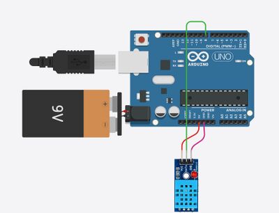
*VCC (DHT11) → 5V (Arduino UNO) | *VCC (DHT11) → 5V (Arduino UNO) | ||
| Line 67: | Line 306: | ||
The data output pin of the DHT11 is connected to digital pin 8 on the Arduino for reading sensor data. | The data output pin of the DHT11 is connected to digital pin 8 on the Arduino for reading sensor data. | ||
A 9V battery provides power to the Arduino UNO through a DC barrel jack adapter, which converts the voltage for safe operation. | |||
====B57861S-SHT31 Connection==== | |||
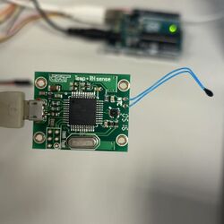
Connect to the computer via a data cable. | |||
<center>[[File:Circuit-diagram.jpg|400px]]</center> | |||
<center>'''DHT11 Sensor Connected to Arduino UNO'''</center> | |||
[[File: | <center> | ||
{| style="margin: auto;" | |||
|- | |||
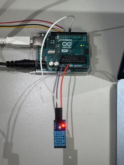
| <center>[[File:Dht11-arduino.jpg|250px]]</center> | |||
| <center>[[File:B57861S-SHT31.jpg|250px]]</center> | |||
|- | |||
| <center>'''DHT11 Sensor Connected to Arduino UNO '''</center> | |||
| <center>'''NTC thermistor B57861S and SHT31 temperature and humidity sensor'''</center> | |||
|} | |||
</center> | |||
===Programming and Uploading Code=== | ===Programming and Uploading Code=== | ||
====DHT11==== | |||
<b>(1)</b>Installing Libraries | |||
*In Arduino IDE, install the DHT Sensor Library by Adafruit and LiquidCrystal_I2C libraries. | *In Arduino IDE, install the DHT Sensor Library by Adafruit and LiquidCrystal_I2C libraries. | ||
<b>(2)</b>Writing Code (Code details omitted) | |||
*Include necessary libraries (DHT). | *Include necessary libraries (DHT). | ||
*Define the DHT11 sensor pin and type. | *Define the DHT11 sensor pin and type. | ||
*In the loop() function, read temperature and humidity data and serial monitor. | *In the loop() function, read temperature and humidity data and serial monitor. | ||
<b>(3)</b>Uploading Code | |||
*Connect Arduino to the computer via USB cable. | *Connect Arduino to the computer via USB cable. | ||
*Select the correct board model and port. | *Select the correct board model and port. | ||
| Line 113: | Line 367: | ||
delay(2000); // Delay between readings | delay(2000); // Delay between readings | ||
} | } | ||
====B57861S-SHT31==== | |||
<b>(1)</b>Installing Toolchain | |||
Install the required tools on your computer to compile and upload code to the Atmel microcontroller: | |||
*AVR-GCC: Compiler for AVR microcontrollers | |||
*AVRDUDE: Utility for uploading firmware | |||
*Make: For building the code using the provided Makefile | |||
Once installed, the system will be ready to compile and upload the firmware provided in the tempsense project. | |||
<b>(2)</b>Writing Code | |||
No manual coding is needed. The firmware is already written in the file tempsense.c. It performs the following tasks: | |||
Reads analog voltage from the NTC thermistor | |||
Computes temperature using an interpolation algorithm | |||
Sends the temperature data via serial output | |||
Temperature calculation can be further refined using the interpolation table or equations provided in thermistorinterpolation.nb (a Mathematica file). | |||
Here is the simplified version of tempsense.c, with only the core functionality preserved: | |||
✅ Reads temperature using an NTC thermistor (via analog ADC input) | |||
✅ Uses PWM to create a high-resolution sampling window for improved ADC accuracy | |||
✅ Outputs raw ADC values over UART at 9600 baud | |||
The following components have been removed: | |||
❌ USB CDC emulation and USB descriptors | |||
❌ SHT31 humidity sensor and I²C communication | |||
❌ Command parsing system and help text | |||
❌ DFU (Device Firmware Upgrade) mode and endpoint interrupt handling | |||
/* Minimal version of tempsense.c | |||
- Only thermistor reading with ADC | |||
- High-resolution sampling using PWM window | |||
- UART output for temperature (9600 baud) | |||
*/ | |||
#define F_CPU 16000000UL | |||
#include <avr/io.h> | |||
#include <util/delay.h> | |||
#include <avr/interrupt.h> | |||
#include <stdlib.h> | |||
#include <stdio.h> | |||
/* ---------------- UART ---------------- */ | |||
void uart_init() { | |||
UBRR1H = 0; | |||
UBRR1L = 103; // 9600 baud @ 16 MHz | |||
UCSR1B = (1 << TXEN1); | |||
UCSR1C = (1 << UCSZ11) | (1 << UCSZ10); | |||
} | |||
void uart_send(char c) { | |||
while (!(UCSR1A & (1 << UDRE1))); | |||
UDR1 = c; | |||
} | |||
void uart_print(const char* s) { | |||
while (*s) uart_send(*s++); | |||
} | |||
void uart_println(const char* s) { | |||
uart_print(s); | |||
uart_send('\r'); | |||
uart_send('\n'); | |||
} | |||
void uart_print_int(int32_t val) { | |||
char buf[16]; | |||
ltoa(val, buf, 10); | |||
uart_print(buf); | |||
} | |||
/* ---------------- PWM ---------------- */ | |||
void pwm_init() { | |||
TC4H = 0x03; OCR4C = 0xE7; // top = 999 | |||
TC4H = 0; OCR4A = 0; // initial duty = 0 | |||
TCCR4A = 0x82; // clear OC4A on compare match | |||
TCCR4B = 0x01; // no prescaler | |||
DDRC |= (1 << PC7); // OC4A output | |||
} | |||
void pwm_set(uint16_t val) { | |||
TC4H = val >> 8; | |||
OCR4A = val & 0xFF; | |||
} | |||
/* ---------------- ADC ---------------- */ | |||
#define WINDOWCONST 5 | |||
#define MAXOFFSETDAC 200 | |||
uint8_t offset_dac_window = 0; | |||
int read_adc(uint8_t ch) { | |||
ADMUX = (1 << REFS0) | (ch & 0x0F); | |||
ADCSRA = (1 << ADEN) | (1 << ADPS2) | (1 << ADPS1) | (1 << ADPS0); | |||
ADCSRA |= (1 << ADSC); | |||
while (ADCSRA & (1 << ADSC)); | |||
return ADC & 0x3FF; | |||
} | |||
uint32_t getfull_adc() { | |||
int rd = read_adc(1); // differential sense (simulated here) | |||
uint32_t retval = ((uint32_t)offset_dac_window) << 9; | |||
if ((rd > 480) && (offset_dac_window < MAXOFFSETDAC)) offset_dac_window++; | |||
else if ((rd < -480) && (offset_dac_window > 0)) offset_dac_window--; | |||
uint16_t offset = offset_dac_window * WINDOWCONST; | |||
if (offset > 999) offset = 999; | |||
pwm_set(offset); | |||
return retval + rd; | |||
} | |||
/* ---------------- Main ---------------- */ | |||
int main(void) { | |||
uart_init(); | |||
pwm_init(); | |||
ADCSRA |= (1 << ADEN); | |||
uart_println("Thermistor temperature readout"); | |||
while (1) { | |||
uint32_t raw = getfull_adc(); | |||
uart_print("Raw ADC: "); | |||
uart_print_int(raw); | |||
uart_println(""); | |||
_delay_ms(1000); | |||
} | |||
} | |||
<b>(3)</b>Uploading Code | |||
Connect the USBasp to the computer. | |||
Compile the firmware to generate a .hex file. | |||
Select the correct microcontroller model. | |||
Upload the firmware using a standard upload tool or the provided upload script. | |||
import serial | |||
import time | |||
# Open the serial port (adjust baudrate according to your device) | |||
ser = serial.Serial('COM4', baudrate=9600, timeout=1) | |||
while True: | |||
# Send the command | |||
ser.write('help\n'.encode()) | |||
# Read all returned lines | |||
result = ser.readlines() | |||
# Print the result | |||
for line in result: | |||
print(line.decode().strip()) | |||
# Optional: wait 1 second before sending the next command | |||
time.sleep(1) | |||
Then important commands: | |||
*ON switches thermistor bias on | |||
*OFF switches thermistor bias off | |||
*ITEMP? returns instantaneous temperature in degree Celsius | |||
*TEMP? returns a low-pass filtered average temperature over 3.2sec | |||
*NTEMP? returns last periodically (100ms) read temperature | |||
*RH? returns relative humidity in percent | |||
*CTEMP? returns Sensirion chip temperature | |||
*WEATHER? Reports both avg temperature and rel humidity | |||
*ALL? Like weather, but returns also chip temp | |||
*HELP prints this help text | |||
This is a thermistor-based thermometer with a nominal resolution of 1mK. | |||
Then, enter ON, followed by WEATHER? to obtain continuous temperature and humidity data. | |||
Once uploaded, the microcontroller will automatically start running the temperature sensing program. | |||
<b>(4)</b>Monitoring Output | |||
After uploading: | |||
*Open a serial terminal | |||
*Set the baud rate to 9600 bps | |||
*The temperature data will be displayed in real-time on the terminal | |||
===Experiment Operation=== | ===Experiment Operation=== | ||
| Line 118: | Line 560: | ||
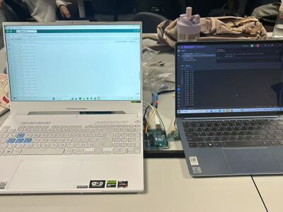
Disconnect USB Power and Connect 9V Battery. | Disconnect USB Power and Connect 9V Battery. | ||
Observe Temperature and Humidity Data on the | Observe Temperature and Humidity Data on the Serial Monitor and record the data. | ||
<center>[[File:Experimental-Procedure.jpg|400px]]</center> | |||
<center>'''Experimental Procedure'''</center> | |||
== Results and Data Analysis == | |||
===Results Overview=== | |||
<center> | |||
{| style="text-align: center; margin: auto;" | |||
|- | |||
| <center>[[File:OutdoorTem.png|300px]]</center> | |||
| <center>[[File:OutdoorHum.jpg|300px]]</center> | |||
| <center>[[File:RainTem.png|300px]]</center> | |||
|- | |||
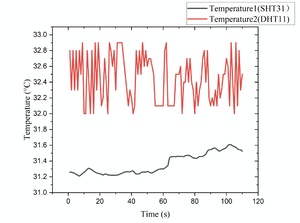
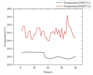
| <center>'''Outdoor Temperature Response Recorded by SHT31 and DHT11 Sensors Over Time'''</center> | |||
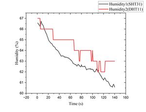
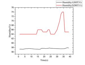
| <center>'''Outdoor Humidity Response Recorded by SHT31 and DHT11 Sensors Over Time'''</center> | |||
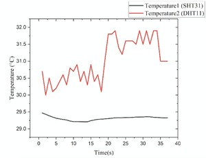
| <center>'''RainyDay Temperature Response Recorded by SHT31 and DHT11 Sensors Over Time'''</center> | |||
|- | |||
| <center>[[File:RainHum.jpg|300px]]</center> | |||
| <center>[[File:RoomTem.png|300px]]</center> | |||
| <center>[[File:RoomHum.jpg|300px]]</center> | |||
|- | |||
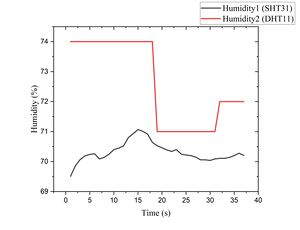
| <center>'''RainyDay Humidity Response Recorded by SHT31 and DHT11 Sensors Over Time'''</center> | |||
| <center>'''Room Temperature Response Recorded by SHT31 and DHT11 Sensors Over Time'''</center> | |||
| <center>'''Room Humidity Response Recorded by SHT31 and DHT11 Sensors Over Time'''</center> | |||
|} | |||
</center> | |||
===Calculate=== | |||
To assess the consistency and performance of the two sensors (SWT Sensor 1 and DHT11 Sensor 2), we calculated the sample variance for each set of measurements across different environments: rainy conditions, indoor room, and canteen. The variance provides a quantitative measure of the spread or variability in sensor readings. | |||
The sample variance was computed using the standard formula: | |||
For a dataset <math>x_1, x_2, \dots, x_n</math>, the sample variance is calculated as: | |||
<center><span style="font-size: 150%;"><math>s^2 = \frac{1}{n - 1} \sum_{i=1}^{n} (x_i - \bar{x})^2</math></span></center> | |||
Where: | |||
<math>s^2</math> = sample variance | |||
<math>n</math> = number of data points | |||
<math>x_i</math> = the <math>i</math>-th data point | |||
<math>\bar{x}</math> = sample mean (average) | |||
Based on the calculation, the result is: | |||
<center>[[File:variance.png|750px]]</center> | |||
<center>'''Variance of Temperature and Humidity Sensor Readings Across Three Environments'''</center> | |||
===Analysis and Conclusion=== | |||
🔹 Final Analysis Based on Project Goals and Experimental Results | |||
The objective of this project was to compare two temperature and humidity sensors'''DHT11''' and '''SHT31-DIS''' under real-world conditions, focusing on their '''cost-effectiveness''', '''ease of integration''', and '''basic accuracy''' in different environments including outdoor, indoor, and rainy conditions. | |||
🔹 Strengths of DHT11 | |||
Despite being known as a low-cost and entry-level sensor, the DHT11 performed surprisingly well in our experiment and demonstrated the following strengths: | |||
* '''Stable and consistent readings''': In all tested environments, the DHT11 provided reasonable and consistent data. For example, in rainy conditions, the humidity variance was only '''1.96 %²''', which is acceptable for many non-critical monitoring tasks. | |||
* '''Good performance in stable indoor conditions''': In the indoor environment, DHT11 showed a temperature variance of only '''0.11 °C²''', compared to SHT31's '''0.03 °C²'''. This shows it is capable of performing well in controlled, less dynamic environments. | |||
* '''Sufficient accuracy for general use''': While it is not suitable for precision applications, DHT11 is accurate enough for '''educational projects''', '''DIY environmental monitors''', and '''smart home systems'''. | |||
* '''Very easy to use and integrate''': The single-wire digital output makes it simple to connect with most microcontrollers, especially for beginners and students. | |||
* '''Highly cost-effective''': One of its greatest advantages is the ability to deliver useful data at a '''very low cost''', making it ideal for '''low-budget or large-scale sensor networks'''. | |||
🔹 Comparison with SHT31-DIS | |||
While the SHT31-DIS clearly offers better '''accuracy''', '''faster response''', and '''broader working range''', our experiment results indicate that the DHT11 still performs well in many practical scenarios, especially when the environmental conditions are stable. Its performance-to-cost ratio is impressive, particularly for general monitoring purposes. | |||
🔹 Conclusion | |||
Although the SHT31-DIS is a better choice for high-precision or industrial applications, the DHT11 '''fully meets the goals of this project''' — providing a practical, reliable, and affordable solution for basic temperature and humidity monitoring. Based on our experimental data and project objectives, we conclude that '''DHT11 is a highly viable option when simplicity, affordability, and sufficient accuracy are prioritized'''. | |||
== References == | == References == | ||
| Line 132: | Line 651: | ||
[4]Aleksić O S, Nikolić P M. Recent advances in NTC thick film thermistor properties and applications[J]. Facta universitatis-series: Electronics and Energetics, 2017, 30(3): 267-284. | [4]Aleksić O S, Nikolić P M. Recent advances in NTC thick film thermistor properties and applications[J]. Facta universitatis-series: Electronics and Energetics, 2017, 30(3): 267-284. | ||
[5]QOLAH Project. (n.d.). Atmel_firmware: tempsense. Retrieved April 1, 2025, from https://qolah.org/Atmel_firmware/tempsense/ | |||
Latest revision as of 19:34, 8 April 2025
Team Member
Chen Andi、Chen Miaoge、Chen Yingnan、Fang Ye
Background
With the advancement of smart home systems, agricultural monitoring, and industrial environmental control, real-time monitoring of ambient temperature and humidity has become increasingly important. Variations in temperature and humidity significantly impact human daily activities, industrial production, and the storage conditions of various products. Traditional temperature and humidity measurement instruments are often expensive or lack real-time data display capabilities. Therefore, designing a low-cost, real-time temperature and humidity monitoring system based on the DHT11 sensor and Arduino holds significant practical and educational value.
Objective
(1) Design and implement a real-time temperature and humidity monitoring system based on Arduino and the DHT11 sensor, capable of continuously acquiring environmental temperature and humidity data. The system is designed to fulfill the following functions:
- Real-time Data Acquisition: Accurately measures the current ambient temperature and humidity.
- Dynamic Data Display: Continuously updates the computer screen to reflect the latest measurement data.
- Low Cost and High Scalability: Suitable for various applications such as smart home systems, agriculture, and warehouse environments, with potential extensions to wireless data transmission and other advanced functionalities.
(2) Compare the Performance of DHT11 and SHT31 Sensors in Different Environments: By simultaneously using the DHT11 and SHT31 sensors, compare the temperature and humidity data measured in both indoor and outdoor environments. Analyze the differences in measurement accuracy, stability, and response time between the two sensors.
(3) Explore the Practical Application and Performance of the DHT11 Sensor: Focus on studying the performance of the DHT11 sensor in dynamically changing environments, particularly under conditions where temperature and humidity fluctuate significantly, and evaluate its suitability and reliability for practical applications.
(4) Optimize Sensor Selection and Application Scenarios: Based on the experimental results, identify the strengths and limitations of both DHT11 and SHT31 sensors, helping to choose the most appropriate sensor for different scenarios. This is particularly relevant for projects where cost is a factor, or where high precision is not the primary concern, and how to efficiently use the DHT11.
Theory
Temperature Measurement
Definition of Temperature
Temperature is a fundamental physical quantity used to characterize the thermal state of a system, determining the direction of heat flow between two bodies. It is typically measured in degrees Celsius (°C), Kelvin (K), or Fahrenheit (°F), depending on the context. In the field of temperature measurement, various devices, including thermocouples, thermistors, and pyrometers, are used to determine temperature across different ranges. Temperature is defined as the measure of the average kinetic energy of the particles in a substance, and it plays a critical role in various natural and technological processes. At a molecular level, temperature correlates with the movement of atoms and molecules: the higher the temperature, the faster the motion of the particles. In the context of thermistors, temperature is directly related to resistance through a thermoresistive effect. Specifically, NTC (Negative Temperature Coefficient) thermistors show a decrease in resistance with an increase in temperature, making them useful for temperature measurement and control in electronics, industrial processes, and other applications requiring precision temperature data.
NTC Thermistors
NTC (negative temperature coefficient) thermistor is a semiconductor device whose resistance value decreases with increasing temperature. This property is mainly due to the conductive mechanism of the semiconductor material: when the temperature increases, the electrons inside the semiconductor gain more energy and jump into the conduction band, increasing the number of free carriers, which reduces the resistance of the material.
The relationship between temperature T (in Kelvin) and resistance R is often described by the Steinhart-Hart equation, which is widely used to model the behavior of thermistors:
The absoute temperature then can be obtained by inverting the equation above:
Where R0 is the resistance at a reference temperature T0 ,B is the material constant of the thermistor, T is the temperature of interest.
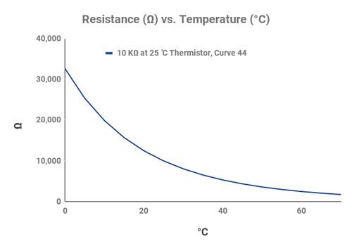
Figure 1 Resistance vs. Temperature Curve for 10 kΩ NTC Thermistor at 25°C
NTC Thermistors exhibit a negative temperature coefficient (NTC), meaning their resistance decreases with an increase in temperature. They are used in various applications such as temperature measurement and compensation in electronics. These thermistors are particularly useful in electronics, air conditioning, and automotive applications due to their high sensitivity and low cost.
Humidity Measurement
Relative Humidity
Relative Humidity (R.H.) is one of the most commonly measured parameters in humidity measurement and plays a critical role in various industrial and commercial applications. It is defined as the ratio of the partial pressure of water vapor in the air (Pw) to the saturation vapor pressure (Ps) at a specific temperature, expressed as a percentage:
Where Pw is the actual water vapor pressure in the air, and Ps is the saturation vapor pressure at the ambient temperature. "When temperature and pressure change, the corresponding water vapor pressure also changes, so the relative humidity will change as well. Relative humidity provides a measure of how much water vapor is present in the air relative to the maximum amount of water vapor the air can hold at a given temperature.
Resistive Humidity Sensors
Resistive humidity sensors operate based on changes in the conductivity of the sensor material as it absorbs water vapor. The resistance of the sensor decreases as the humidity increases, which is the primary transduction mechanism. These sensors typically utilize materials with significant changes in conductivity in response to moisture content, making them suitable for a variety of humidity sensing applications.
Equipment Required
DHT11
DHT11 is a temperature and humidity composite sensor with calibrated digital signal output, suitable for the measurement of ambient temperature and humidity. It adopts special digital module acquisition technology, which can provide high reliability and long-term stability, and is widely used in environmental monitoring, industrial control, home automation and other fields.
Basic Features and Specifications
Internal structure of the DHT11 sensor
DHT11 mainly consists of the following three parts:
(1)Resistive moisture sensing element: used to measure air humidity.
(2)NTC (negative temperature coefficient thermistor) temperature measuring element: used to measure the ambient temperature.
(3)Internal microcontroller: used for data processing, calibration and communication.
During the measurement process, the DHT11 sensor converts the temperature and humidity data into a standard digital signal through an internal signal conditioning circuit and transmits the data through a Single Wire protocol.
Working principle
(1) Temperature Sensing: Use an NTC thermistor whose resistance varies with temperature. The onboard microcontroller converts this change into a calibrated digital signal.
(2) Humidity Sensing: A capacitive or resistive humidity sensing element detects the moisture content in the air by measuring changes in electrical resistance or capacitance caused by water vapor. The onboard microcontroller then converts these changes into a humidity percentage.
Pin specification

Protocol and Data Format
The DHT11 uses a single-wire protocol to communicate with a microcontroller. After the microcontroller sends a start signal, the DHT11 switches from low-power mode to high-speed mode. It waits for the start signal to finish and then sends a response signal, followed by a data transmission.
A complete data transmission consists of 40 bits, sent in order from the most significant bit to the least significant bit.
Data format:
• 8 bits: Humidity integer
• 8 bits: Humidity decimal
• 8 bits: Temperature integer
• 8 bits: Temperature decimal
• 8 bits: Checksum
Totaling 5 bytes (40 bits).
Since the resolution only ensures whole numbers, the decimal parts are always 0. The checksum is the sum of the first four bytes. The purpose of the checksum is to ensure accurate data transmission.
The DHT11 only performs temperature and humidity measurements once it receives a start signal from the host.
If no start signal is received, the DHT11 will not automatically perform measurements. After the data collection is complete and transmission ends, the DHT11 automatically switches back to low-speed mode.
Operation Timing

(1) Host Sends Initialization Signal
The initialization process of the DHT11 is divided into the initialization signal and the response signal.
First, the host pulls the data line low for at least 18 ms, then pulls it high again and waits for 20–40 μs (typically 30 μs). At this point, the initialization signal has been completely sent.

In slave mode, once the DHT11 receives the start signal, it triggers a temperature and humidity acquisition. If the start signal from the host is not received, the DHT11 will not actively perform temperature and humidity acquisition. After data collection, it switches to low-speed mode.
(2) DHT11 Sends Response Signal
After detecting the start signal, the DHT11 triggers a sampling process, pulls the data line low for 80 μs to indicate a response signal, and notifies the host that the data is ready. Then it pulls the line high for another 80 μs before beginning to transmit data. If the response signal detected is high level instead, the DHT11 initialization has failed—please check if the wiring is correct.
Once the initialization signal is completely sent, if a low level is detected on the bus, start counting every 1 μs until the bus goes high, measuring the low-level time. After the bus is pulled high, start counting again to detect the following 80 μs high-level period. If this 80 μs high level is detected after the response signal, data reception is about to begin.
In practice, the DHT11's response time may not be exactly 80 μs and often fluctuates. Generally, if the response occurs within 20–100 μs, it can be considered successful.
(3) Data Transmission
After pulling the data line high for 80 μs, the DHT11 begins transmitting data. Each bit of data starts with a 50 μs low-level signal, indicating to the host that a bit is about to be sent. The length of the following high-level signal determines whether the bit is a ‘0’ or a ‘1’. If the data line is pulled high after the 50 μs low level:
• A high level lasting 26–28 μs indicates a “0”
• A high level lasting 70 μs indicates a “1”
After the last (40th) bit is transmitted, the DHT11 pulls the line low for 50 μs, indicating the end of data transmission. Then, the bus is pulled high by the pull-up resistor, entering an idle state.
 |
 |
Analysis of advantages and disadvantages
(1) Advantages
• Calibrated digital output, easy to use
• Ultra-low power consumption
• Long communication distance, simple interface
• Very low cost, suitable for mass deployment
(2) Disadvantages
• Temperature error ±2 °C, humidity error ±5% RH
• Minimum sampling interval ≥ 1 s, not suitable for high-speed acquisition
• Certain limitations on usage environment
• Not suitable for precision measurement or industrial high-accuracy applications
- Electronic display
- Arduino
- DuPont Line
- battery-9V
SHT31-DIS
SHT31-DIS is the next generation of Sensirion’s temperature and humidity sensors. It builds on a newCMOSens® sensor chip that is at the heart of Sensirion’s new humidity and temperature platform. The SHT31-DIS has increased intelligence, reliability, and improved accuracy specifications compared to its predecessor. Its functionality includes enhanced signal processing, two distinctive and user-selectable I2C addresses, and communication speeds of up to 1 MHz.
Basic Features and Specifications
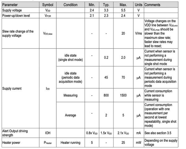
• High accuracy: The SHT31-DIS offers a typical accuracy of ±2% RH for humidity and ±0.3°C for temperature.
• Fast measurement: It has a fast startup time and short measurement cycles, enabling rapid readings.
• Low power consumption: The sensor operates in low power modes, making it ideal for battery-powered applications.
• I2C Communication: The sensor communicates over the I2C interface, supporting clock speeds up to 1 MHz and providing flexibility in address configuration.
Internal structure of the SHT31-DIS sensor
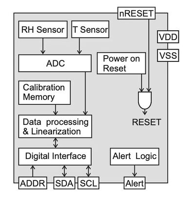
• Humidity sensing element: This is a capacitive humidity sensor that detects moisture content in the air. It measures changes in capacitance caused by water vapor.
• Temperature sensing element: The temperature is measured using an integrated thermistor. The resistance of the thermistor changes with temperature, and the onboard microcontroller converts this change into a temperature value.
• Onboard microcontroller: It processes the data, performs calibration, and communicates with the external system via I2C.
Working principle
• Humidity Sensing: The capacitive sensor detects the moisture content by measuring changes in capacitance. The onboard microcontroller processes this change and outputs the relative humidity as a digital value.
• Temperature Sensing: The thermistor's resistance varies with temperature. The microcontroller converts this variation into a temperature reading, which is then output digitally.
• Data Transmission: The onboard microcontroller converts temperature and humidity values into digital signals and transmit to the host system via the I2C bus.
Pin specification
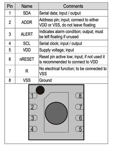
Protocol and Data Format
The SHT31-DIS uses the I2C protocol for communication. The sensor provides a 16-bit data output for both temperature and humidity measurements.
The typical data format includes:
• Humidity (16 bits): Two bytes representing relative humidity.
• Temperature (16 bits): Two bytes representing temperature.
• Checksum (8 bits): For error detection.
Operation Timing
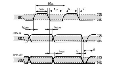
• Initialization: When powered on, the sensor enters a low-power idle state. The host must send an I2C command to begin measurement.
• Measurement Commands: The sensor can operate in different modes, such as single-shot mode or periodic data acquisition mode. In single-shot mode, the sensor takes one measurement at a time, while in periodic mode, it continuously measures and sends data at a set frequency.
Analysis of advantages and disadvantages
(1) Advantages
• High Accuracy and Stability:
The SHT31-DIS sensor provides high accuracy with ±2% RH for humidity and ±0.3°C for temperature measurements, making it suitable for applications that require high precision. It utilizes CMOSens® technology, which ensures long-term stability and high reliability. The sensor is factory-calibrated and linearized, ensuring consistent and accurate measurements.
• Fast Response Time and Start-Up:
The SHT31-DIS has a fast start-up and measurement time, enabling quick data collection. This feature is beneficial for applications where fast response to environmental changes is needed.
• Low Power Consumption:
It features ultra-low power consumption in idle state and during measurement, making it suitable for battery-operated or low-power applications. The sensor can operate in a low-power mode when not actively measuring.
• Wide Supply Voltage Range: The SHT31-DIS operates within a wide supply voltage range from 2.4V to 5.5V, allowing it to be used in a variety of applications with different power supply requirements.
(2) Disadvantages
• Limited Measurement Range:
While the SHT31-DIS covers a humidity range from 0% to 100% RH and a temperature range from -40°C to 125°C, it may not be suitable for applications that require measurements beyond these ranges
• Higher Cost Compared to Simpler Sensors:
The SHT31-DIS is more expensive than simpler sensors like the DHT11, which may be a disadvantage in applications where cost is a significant concer
• Response Time Affected by Environmental Conditions:
While the response time is generally fast, the sensor's response can be influenced by external conditions like airflow and temperature, which may affect its accuracy in some scenarios
Experiment Steps
Circuit Connection
DHT11 Connection
- VCC (DHT11) → 5V (Arduino UNO)
The VCC pin of the sensor is connected to the 5V power supply pin on the Arduino to provide power.
- GND (DHT11) → GND (Arduino UNO)
The ground pin of the sensor is connected to the ground pin on the Arduino.
- OUT (DHT11) → Digital Pin 8 (Arduino UNO)
The data output pin of the DHT11 is connected to digital pin 8 on the Arduino for reading sensor data.
A 9V battery provides power to the Arduino UNO through a DC barrel jack adapter, which converts the voltage for safe operation.
B57861S-SHT31 Connection
Connect to the computer via a data cable.
 |
 |
Programming and Uploading Code
DHT11
(1)Installing Libraries
- In Arduino IDE, install the DHT Sensor Library by Adafruit and LiquidCrystal_I2C libraries.
(2)Writing Code (Code details omitted)
- Include necessary libraries (DHT).
- Define the DHT11 sensor pin and type.
- In the loop() function, read temperature and humidity data and serial monitor.
(3)Uploading Code
- Connect Arduino to the computer via USB cable.
- Select the correct board model and port.
 #include "DHT.h"
 #define DHTPIN 8       // Pin where the sensor is connected
 #define DHTTYPE DHT11  // Sensor type
 DHT dht(DHTPIN, DHTTYPE);
 void setup() {
 Serial.begin(9600); // Initialize the serial monitor
 dht.begin();        // Initialize the sensor
 }
 void loop() {
 float humidity = dht.readHumidity();            // Read humidity
 float temperatureC = dht.readTemperature();     // Temperature in Celsius
 float temperatureF = dht.readTemperature(true); // Temperature in Fahrenheit
 float temperatureK = temperatureC + 273.15;     // Temperature in Kelvin
 if (isnan(humidity) || isnan(temperatureC)) {
   Serial.println("Error reading data!");
   return;
 }
 // Output data to the serial monitor
 Serial.print("Temperature: ");
 Serial.print(temperatureC);
 Serial.print("°C, ");
 Serial.print(temperatureF);
 Serial.print("°F, ");
 Serial.print(temperatureK);
 Serial.println("K");
 Serial.print("Humidity: ");
 Serial.print(humidity);
 Serial.println("%");
 delay(2000); // Delay between readings
 }
B57861S-SHT31
(1)Installing Toolchain
Install the required tools on your computer to compile and upload code to the Atmel microcontroller:
- AVR-GCC: Compiler for AVR microcontrollers
- AVRDUDE: Utility for uploading firmware
- Make: For building the code using the provided Makefile
Once installed, the system will be ready to compile and upload the firmware provided in the tempsense project.
(2)Writing Code
No manual coding is needed. The firmware is already written in the file tempsense.c. It performs the following tasks:
Reads analog voltage from the NTC thermistor
Computes temperature using an interpolation algorithm
Sends the temperature data via serial output
Temperature calculation can be further refined using the interpolation table or equations provided in thermistorinterpolation.nb (a Mathematica file).
Here is the simplified version of tempsense.c, with only the core functionality preserved:
✅ Reads temperature using an NTC thermistor (via analog ADC input)
✅ Uses PWM to create a high-resolution sampling window for improved ADC accuracy
✅ Outputs raw ADC values over UART at 9600 baud
The following components have been removed:
❌ USB CDC emulation and USB descriptors
❌ SHT31 humidity sensor and I²C communication
❌ Command parsing system and help text
❌ DFU (Device Firmware Upgrade) mode and endpoint interrupt handling
/* Minimal version of tempsense.c
  - Only thermistor reading with ADC
  - High-resolution sampling using PWM window
  - UART output for temperature (9600 baud)
*/
#define F_CPU 16000000UL
#include <avr/io.h>
#include <util/delay.h>
#include <avr/interrupt.h>
#include <stdlib.h>
#include <stdio.h>
/* ---------------- UART ---------------- */
void uart_init() {
   UBRR1H = 0;
   UBRR1L = 103; // 9600 baud @ 16 MHz
   UCSR1B = (1 << TXEN1);
   UCSR1C = (1 << UCSZ11) | (1 << UCSZ10);
}
void uart_send(char c) {
   while (!(UCSR1A & (1 << UDRE1)));
   UDR1 = c;
}
void uart_print(const char* s) {
   while (*s) uart_send(*s++);
}
void uart_println(const char* s) {
   uart_print(s);
   uart_send('\r');
   uart_send('\n');
}
void uart_print_int(int32_t val) {
   char buf[16];
   ltoa(val, buf, 10);
   uart_print(buf);
}
/* ---------------- PWM ---------------- */
void pwm_init() {
   TC4H = 0x03; OCR4C = 0xE7; // top = 999
   TC4H = 0; OCR4A = 0;       // initial duty = 0
   TCCR4A = 0x82;             // clear OC4A on compare match
   TCCR4B = 0x01;             // no prescaler
   DDRC |= (1 << PC7);        // OC4A output
}
void pwm_set(uint16_t val) {
   TC4H = val >> 8;
   OCR4A = val & 0xFF;
}
/* ---------------- ADC ---------------- */
#define WINDOWCONST 5
#define MAXOFFSETDAC 200
uint8_t offset_dac_window = 0;
int read_adc(uint8_t ch) {
   ADMUX = (1 << REFS0) | (ch & 0x0F);
   ADCSRA = (1 << ADEN) | (1 << ADPS2) | (1 << ADPS1) | (1 << ADPS0);
   ADCSRA |= (1 << ADSC);
   while (ADCSRA & (1 << ADSC));
   return ADC & 0x3FF;
}
uint32_t getfull_adc() {
   int rd = read_adc(1); // differential sense (simulated here)
   uint32_t retval = ((uint32_t)offset_dac_window) << 9;
   if ((rd > 480) && (offset_dac_window < MAXOFFSETDAC)) offset_dac_window++;
   else if ((rd < -480) && (offset_dac_window > 0)) offset_dac_window--;
   uint16_t offset = offset_dac_window * WINDOWCONST;
   if (offset > 999) offset = 999;
   pwm_set(offset);
   return retval + rd;
}
/* ---------------- Main ---------------- */
int main(void) {
   uart_init();
   pwm_init();
   ADCSRA |= (1 << ADEN);
   uart_println("Thermistor temperature readout");
  while (1) {
       uint32_t raw = getfull_adc();
       uart_print("Raw ADC: ");
       uart_print_int(raw);
       uart_println("");
       _delay_ms(1000);
   }
}
(3)Uploading Code
Connect the USBasp to the computer.
Compile the firmware to generate a .hex file.
Select the correct microcontroller model.
Upload the firmware using a standard upload tool or the provided upload script.
import serial
import time
# Open the serial port (adjust baudrate according to your device)
ser = serial.Serial('COM4', baudrate=9600, timeout=1)
 while True:
   # Send the command
   ser.write('help\n'.encode())
   # Read all returned lines
   result = ser.readlines()
   # Print the result
   for line in result:
       print(line.decode().strip())
   # Optional: wait 1 second before sending the next command
   time.sleep(1)
Then important commands:
- ON switches thermistor bias on
- OFF switches thermistor bias off
- ITEMP? returns instantaneous temperature in degree Celsius
- TEMP? returns a low-pass filtered average temperature over 3.2sec
- NTEMP? returns last periodically (100ms) read temperature
- RH? returns relative humidity in percent
- CTEMP? returns Sensirion chip temperature
- WEATHER? Reports both avg temperature and rel humidity
- ALL? Like weather, but returns also chip temp
- HELP prints this help text
This is a thermistor-based thermometer with a nominal resolution of 1mK.
Then, enter ON, followed by WEATHER? to obtain continuous temperature and humidity data.
Once uploaded, the microcontroller will automatically start running the temperature sensing program.
(4)Monitoring Output
After uploading:
- Open a serial terminal
- Set the baud rate to 9600 bps
- The temperature data will be displayed in real-time on the terminal
Experiment Operation
Disconnect USB Power and Connect 9V Battery.
Observe Temperature and Humidity Data on the Serial Monitor and record the data.
Results and Data Analysis
Results Overview
Calculate
To assess the consistency and performance of the two sensors (SWT Sensor 1 and DHT11 Sensor 2), we calculated the sample variance for each set of measurements across different environments: rainy conditions, indoor room, and canteen. The variance provides a quantitative measure of the spread or variability in sensor readings.
The sample variance was computed using the standard formula:
For a dataset , the sample variance is calculated as:
Where:
= sample variance
= number of data points
= the -th data point
= sample mean (average)
Based on the calculation, the result is:

Analysis and Conclusion
🔹 Final Analysis Based on Project Goals and Experimental Results
The objective of this project was to compare two temperature and humidity sensorsDHT11 and SHT31-DIS under real-world conditions, focusing on their cost-effectiveness, ease of integration, and basic accuracy in different environments including outdoor, indoor, and rainy conditions.
🔹 Strengths of DHT11
Despite being known as a low-cost and entry-level sensor, the DHT11 performed surprisingly well in our experiment and demonstrated the following strengths:
- Stable and consistent readings: In all tested environments, the DHT11 provided reasonable and consistent data. For example, in rainy conditions, the humidity variance was only 1.96 %², which is acceptable for many non-critical monitoring tasks.
- Good performance in stable indoor conditions: In the indoor environment, DHT11 showed a temperature variance of only 0.11 °C², compared to SHT31's 0.03 °C². This shows it is capable of performing well in controlled, less dynamic environments.
- Sufficient accuracy for general use: While it is not suitable for precision applications, DHT11 is accurate enough for educational projects, DIY environmental monitors, and smart home systems.
- Very easy to use and integrate: The single-wire digital output makes it simple to connect with most microcontrollers, especially for beginners and students.
- Highly cost-effective: One of its greatest advantages is the ability to deliver useful data at a very low cost, making it ideal for low-budget or large-scale sensor networks.
🔹 Comparison with SHT31-DIS
While the SHT31-DIS clearly offers better accuracy, faster response, and broader working range, our experiment results indicate that the DHT11 still performs well in many practical scenarios, especially when the environmental conditions are stable. Its performance-to-cost ratio is impressive, particularly for general monitoring purposes.
🔹 Conclusion
Although the SHT31-DIS is a better choice for high-precision or industrial applications, the DHT11 fully meets the goals of this project — providing a practical, reliable, and affordable solution for basic temperature and humidity monitoring. Based on our experimental data and project objectives, we conclude that DHT11 is a highly viable option when simplicity, affordability, and sufficient accuracy are prioritized.
References
[1]BU Y, LUO X, CHEN Y. Temperature and Humidity Acquisition System Based on Sensor DHT11[J]. Computer and Modernization, 2013, 1(11): 133.
[2]Srivastava D, Kesarwani A, Dubey S. Measurement of Temperature and Humidity by using Arduino Tool and DHT11[J]. International Research Journal of Engineering and Technology (IRJET), 2018, 5(12): 876-878.
[3]Lee C Y, Lee G B. Humidity sensors: a review[J]. Sensor Letters, 2005, 3(1-2): 1-15.
[4]Aleksić O S, Nikolić P M. Recent advances in NTC thick film thermistor properties and applications[J]. Facta universitatis-series: Electronics and Energetics, 2017, 30(3): 267-284.
[5]QOLAH Project. (n.d.). Atmel_firmware: tempsense. Retrieved April 1, 2025, from https://qolah.org/Atmel_firmware/tempsense/
