STM32-Based IMU Attitude Estimation: Difference between revisions
| (41 intermediate revisions by the same user not shown) | |||
| Line 1: | Line 1: | ||
__FORCETOC__ | __FORCETOC__ | ||
This project involves using an STM32 microcontroller and an MPU6050 sensor module to measure angular velocity and acceleration. The collected sensor data will be processed to determine the attitude angles (roll, pitch, and yaw) of the system. The project will include sensor calibration, data filtering (e.g., complementary or Kalman filter), and real-time angle computation for accurate motion tracking applications. | This project involves using an STM32 microcontroller and an MPU6050 sensor module to measure angular velocity and acceleration. The collected sensor data will be processed to determine the attitude angles (roll, pitch, and yaw) of the system. The project will include sensor calibration, data filtering (e.g., complementary or Kalman filter), and real-time angle computation for accurate motion tracking applications. | ||
== Introduction == | == Introduction == | ||
In this project, we built a simple attitude estimation system using the STM32F103C8T6 microcontroller and the MPU6050 inertial measurement unit (IMU). The MPU6050 contains a 3-axis accelerometer and a 3-axis gyroscope, which together allow us to sense both linear acceleration and angular velocity in space. | |||
Our goal was to estimate the orientation of the sensor in real time—specifically the roll, pitch, and yaw angles—by processing the raw physical signals output by the sensor. The core idea is based on how physical forces like gravity and rotational motion affect the internal elements of MEMS sensors, and how these effects can be digitized and interpreted. | |||
To make the system work, we wrote low-level I²C communication routines to read data directly from the MPU6050 registers. The raw measurements were then converted into meaningful physical quantities, and passed into a complementary filter, which combines accelerometer and gyroscope data to produce smoother and more stable angle estimates. | |||
Updating the angles in real time | The main steps of the project include: | ||
* Reading raw acceleration and gyroscope data via I²C | |||
* Calibrating the sensor to reduce offset and random noise | |||
* Computing roll and pitch using a complementary filter | |||
* Updating and displaying the estimated angles in real time on an OLED screen | |||
Although this system is relatively simple, it closely reflects the principles used in real-world applications like drone stabilization, smartphone orientation sensing, and robot balancing. More importantly, it helps us explore how sensor physics—particularly the detection of inertial forces—can be harnessed in embedded systems to measure motion and orientation. | |||
== Team Members == | == Team Members == | ||
| Line 24: | Line 24: | ||
FAN XUTING | FAN XUTING | ||
== Project Overview == | == Project Overview == | ||
The core idea of this project is to estimate the orientation (attitude) of an object in space using inertial sensor data. We used the MPU6050 module, which integrates a 3-axis accelerometer and a 3-axis gyroscope, to measure two different physical quantities: linear acceleration and angular velocity. These are fundamental mechanical observables when analyzing motion. | |||
The | The data from the sensor is acquired through I²C communication using the STM32F103C8T6 microcontroller. However, the raw measurements—especially from the gyroscope—tend to drift over time, and the accelerometer is sensitive to external vibrations. Therefore, we applied a complementary filter to combine the short-term precision of the gyroscope with the long-term stability of the accelerometer. This approach helps us reduce noise and improve the reliability of the estimated angles. | ||
Our objective is to continuously compute the roll, pitch, and yaw angles of the sensor in real time. In practice, only roll and pitch can be estimated reliably without a magnetometer, since yaw depends on integrating rotational velocity around the vertical axis and is subject to drift. | |||
Systems like this are commonly found in drones, balancing robots, camera gimbals, and even smartphones for orientation detection. In our project, we replicated the basic functionality of such systems on a smaller scale in order to understand how physical quantities—like gravity and rotation—can be sensed, processed, and interpreted through embedded electronics. | |||
== Setup == | == Setup == | ||
=== Equipment === | === Equipment === | ||
The following components were used to build our attitude estimation system: | |||
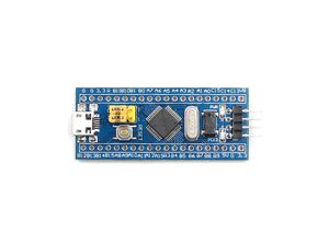
* **STM32F103C8T6 ("Blue Pill")** – A low-cost 32-bit microcontroller used here to handle I²C communication, filtering, and OLED output. | |||
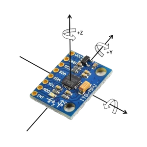
* **MPU6050** – A 6-axis IMU that combines a 3-axis accelerometer (for sensing gravity and linear motion) and a 3-axis gyroscope (for measuring angular velocity). | |||
* **USB to TTL Serial Converter** – Used mainly during development to upload programs to the STM32 and read data from the serial port. | |||
* **Breadboard and jumper wires** – For making temporary connections during prototyping. | |||
* **3.3V Power Supply** – The MPU6050 operates at 3.3V, which is provided by the STM32 board itself. | |||
The MPU6050 is connected to the STM32 using the I²C protocol. I²C is widely used in sensor interfacing due to its simplicity and ability to handle multiple devices over just two lines (SDA and SCL). | |||
[[File:Stm32c8t6.jpg|center|thumb|300px|STM32F103C8T6 "Blue Pill" development board]] | |||
=== Wiring / Circuit Overview === | === Wiring / Circuit Overview === | ||
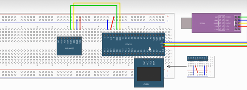
The sensor communicates with the STM32 via I²C, and the wiring is shown below: | |||
{| class="wikitable" | {| class="wikitable" | ||
! MPU6050 Pin !! STM32 Pin !! Notes | ! MPU6050 Pin !! STM32 Pin !! Notes | ||
|- | |- | ||
| VCC || 3.3V || | | VCC || 3.3V || Sensor powered by STM32 | ||
|- | |- | ||
| GND || GND || Common ground | | GND || GND || Common ground reference | ||
|- | |- | ||
| SDA || PB7 || | | SDA || PB7 || I²C data line | ||
|- | |- | ||
| SCL || PB6 || | | SCL || PB6 || I²C clock line | ||
|} | |} | ||
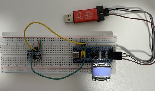
Below are two views of the hardware setup: a breadboard diagram and an abstract schematic: | |||
<div style="display: flex; gap: | <div style="display: flex; gap: 10px; align-items: center;"> | ||
[[File:Imu circuit diagram.png|thumb| | [[File:Imu circuit diagram.png|center|thumb|500px|Breadboard wiring diagram]] | ||
[[File:Schematic diagram of electrical connections.jpeg|thumb| | [[File:Schematic diagram of electrical connections.jpeg|center|thumb|500px|Schematic representation of connections]] | ||
</div> | </div> | ||
=== Software & Code === | |||
The firmware was written in C using STM32's standard peripheral libraries. The program runs in a loop, repeatedly collecting data from the MPU6050 and computing the corresponding attitude angles in real time. | |||
The main software tasks are as follows: | |||
* '''Initialize I²C interface''' – Configure STM32 to communicate with the MPU6050 using the I²C protocol. | |||
* '''Set up MPU6050''' – Select the measurement range for both the accelerometer and gyroscope, and enable continuous data output. | |||
* '''Read raw sensor values''' – Acquire unprocessed data from the accelerometer and gyroscope registers. | |||
* '''Convert to physical units''' – Translate raw values into real-world quantities: | |||
* Acceleration in ''g'' (gravitational units) | |||
* Angular velocity in ''°/s'' | |||
* '''Estimate angles''' – Apply a complementary filter to combine the short-term precision of the gyroscope and the long-term stability of the accelerometer. The filter uses the formula: | |||
<math> | |||
\theta = \alpha \cdot (\theta_{\text{prev}} + \omega \cdot \Delta t) + (1 - \alpha) \cdot \theta_{\text{acc}} | |||
</math> | |||
* '''Output the result''' – Display the roll and pitch angles on the OLED screen. Optionally, angles can also be printed to the serial terminal for monitoring. | |||
The system updates approximately every 10 milliseconds (100 Hz), which is fast enough to track slow and moderate human motion smoothly. | |||
== Theory & Angle Estimation == | |||
To estimate the orientation (attitude) of an object using the MPU6050, we need to understand the physical meaning of the quantities it measures. The accelerometer responds to linear acceleration (including gravity), while the gyroscope senses angular velocity. By interpreting and combining these outputs, we can reconstruct the rotation of the sensor in space. | |||
=== Sensor Principles === | |||
The MPU6050 is a MEMS-based 6-axis Inertial Measurement Unit (IMU). Internally, it contains: | |||
* '''3-axis accelerometer''' – measures linear acceleration along the X, Y, and Z axes, in units of ''g''. | |||
* '''3-axis gyroscope''' – measures angular velocity around the X, Y, and Z axes, in ''°/s''. | |||
These two types of data correspond to physical forces acting on the sensor: | |||
* The accelerometer reflects the direction and magnitude of gravity (when stationary) or combined forces (when moving). | |||
* The gyroscope provides information about how fast the object is rotating around each axis. | |||
By combining both types of data, we can estimate the orientation of the sensor relative to a fixed reference frame. | |||
[[File:MPU6050.png|center|thumb|300px|MPU6050 breakout board showing the chip and I²C interface]] | |||
=== Attitude Angles: Roll, Pitch, Yaw === | |||
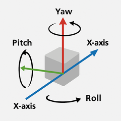
Attitude in 3D space is commonly expressed using three angles: | |||
{| class="wikitable" | |||
! Angle !! Axis !! Description | |||
|- | |||
| Roll || X-axis || Tilting left and right | |||
|- | |||
| Pitch || Y-axis || Tilting forward and backward | |||
|- | |||
| Yaw || Z-axis || Rotating around the vertical axis | |||
|} | |||
In our project, we focus on roll and pitch. Yaw is difficult to measure accurately without a magnetometer, because the accelerometer does not respond to rotation around the vertical axis, and gyroscope-based yaw accumulates drift over time. | |||
[[File:roll_pitch_yaw_axes.png|center|thumb|240px|Roll (X), Pitch (Y), and Yaw (Z) in 3D space]] | |||
=== Using the Accelerometer === | |||
When the sensor is at rest or moving slowly, the accelerometer mainly senses the Earth's gravity. We can use the direction of this gravity vector to estimate the tilt angles with respect to the horizontal plane. Using basic trigonometry: | |||
<math> | |||
\text{pitch} = \arctan\left( \frac{a_x}{\sqrt{a_y^2 + a_z^2}} \right) | |||
</math> | |||
<math> | |||
\text{roll} = \arctan\left( \frac{a_y}{\sqrt{a_x^2 + a_z^2}} \right) | |||
</math> | |||
These estimates are relatively stable when the sensor is static but become noisy during motion, since linear acceleration disturbs the gravity vector. | |||
=== Using the Gyroscope === | |||
The gyroscope gives angular velocity ω (in ''°/s''), which can be integrated over time to estimate changes in orientation: | |||
<math> | |||
\theta = \theta_{\text{prev}} + \omega \cdot \Delta t | |||
</math> | |||
However, this method suffers from drift because small measurement errors accumulate over time. | |||
=== Complementary Filter === | |||
To reduce drift while keeping responsiveness, we apply a complementary filter, which fuses gyroscope and accelerometer data. The gyroscope provides short-term accuracy, while the accelerometer corrects long-term drift. | |||
<math> | |||
\theta = \alpha \cdot (\theta_{\text{prev}} + \omega \cdot \Delta t) + (1 - \alpha) \cdot \theta_{\text{acc}} | |||
</math> | |||
Where: | |||
* <math>\omega</math> is the angular velocity from the gyroscope | |||
* <math>\theta_{\text{acc}}</math> is the angle derived from the accelerometer | |||
* <math>\alpha</math> is a constant between 0.95 and 0.98 | |||
This gives us smooth and relatively accurate estimates for roll and pitch in real time. | |||
== Results == | |||
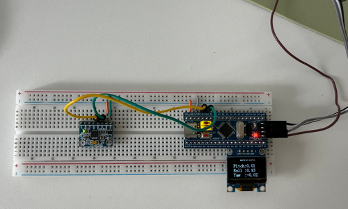
After completing the sensor initialization, calibration, and complementary filter implementation, we tested our system by manually changing the orientation of the MPU6050 module and observing the real-time calculated attitude angles: pitch, roll, and yaw. These values were displayed on the OLED screen in real time. | |||
=== Initial State === | |||
In the initial state, the sensor was placed flat and stationary on the table. The calculated angles were close to zero, fluctuating slightly within ±1° due to sensor noise and environmental vibration. | |||
[[File:pitchrollyaw_initial.png|center|thumb|500px|Initial state: pitch ≈ 0°, roll ≈ 0°, yaw ≈ 0° (flat and stable).]] | |||
=== Pitch Variation=== | |||
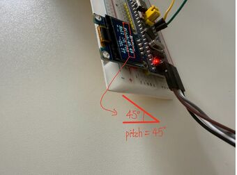
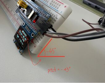
We manually tilted the sensor forward and backward around the Y-axis to generate positive and negative pitch angles. | |||
<div style="display: flex; gap: 30px; justify-content: center;"> | |||
<div style="text-align: center;"> | |||
[[File:pitch_positive.jpeg|thumb|340px|Pitch ≈ +45°]] | |||
</div> | |||
<div style="text-align: center;"> | |||
[[File:pitch_negative.jpeg|thumb|340px|Pitch ≈ -45°]] | |||
</div> | |||
</div> | |||
The pitch angle responded clearly and symmetrically to changes in tilt. The results remained stable when holding the angle. | |||
=== Roll Variation === | |||
Next, we tilted the sensor side-to-side around the X-axis to test roll estimation. | |||
<div style="display: flex; gap: 30px; justify-content: center;"> | |||
<div style="text-align: center;"> | |||
[[File:roll_positive.jpeg|thumb|340px|Roll ≈ +45°]] | |||
</div> | |||
<div style="text-align: center;"> | |||
[[File:roll_negative.jpeg|thumb|340px|Roll ≈ -45°]] | |||
</div> | |||
</div> | |||
The roll angle also showed accurate and consistent results. There was some fluctuation due to hand-held movement, but the trend was clear and repeatable. | |||
=== Yaw Rotation === | |||
Since our yaw angle is calculated by integrating the Z-axis angular velocity, it is expected to drift over time. However, for short-term motion, it could still reflect relative rotation. We rotated the device on a flat surface and observed the change. | |||
<div style="display: flex; gap: 30px; justify-content: center;"> | |||
<div style="text-align: center;"> | |||
[[File:yaw_0deg.jpeg|thumb|340px|Yaw ≈ 0°]] | |||
</div> | |||
<div style="text-align: center;"> | |||
[[File:yaw_90deg.jpeg|thumb|340px|Yaw ≈ 90°]] | |||
</div> | |||
</div> | |||
The yaw angle changed appropriately during rotation. However, due to the lack of a magnetometer, long-term drift is still present and was not corrected in our system. | |||
=== Summary === | |||
The table below summarizes the approximate angles observed during different manual movements. The "Reference" column represents rough estimates of the sensor orientation based on intuition and relative movement, not exact measured angles. | |||
{| class="wikitable" | |||
! Test Condition !! Estimated Tilt !! Measured Angle (OLED) !! Observation | |||
|- | |||
| Flat (Initial) || ≈ 0° || 0° ± 1° || Stable near zero | |||
|- | |||
| Pitch Forward || ~ +45° || +46° || Correct trend | |||
|- | |||
| Pitch Backward || ~ -45° || -46° || Correct trend | |||
|- | |||
| Roll Right || ~ +45° || +46° || Correct trend | |||
|- | |||
| Roll Left || ~ -45° || -48° || Correct trend | |||
|- | |||
| Yaw No Rotation || ~ 0° || 0° || As expected | |||
|- | |||
| Yaw Rotated Clockwise || ~ +90° || +91° || Matches rotation | |||
|} | |||
Note: The reference angles were estimated by eye during manual movement. No precise angle measurement tools were used. | |||
Pitch and roll estimation was stable and consistent throughout the tests. The angle values responded smoothly to manual tilting and aligned well with expected trends within an approximate ±45° range. | |||
Yaw angle changes were visible and directionally accurate during short-term rotation, but drifted over time due to the lack of a magnetometer for correction. | |||
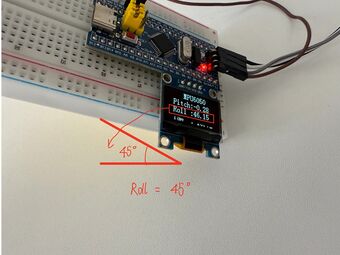
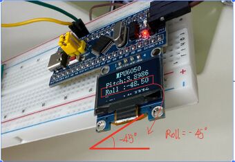
All three angles were displayed clearly on the OLED screen and updated in real time at approximately 100 Hz. | |||
Overall, the complementary filter worked effectively for basic attitude estimation using only the MPU6050 sensor, especially for roll and pitch. The system demonstrates reliable performance for short-term orientation tracking without external reference. | |||
== Discussion == | |||
=== Accuracy and Stability of Roll and Pitch === | |||
The complementary filter worked well in estimating roll and pitch angles. These two values stayed stable when the sensor was stationary, and responded predictably when the module was manually tilted. The accelerometer provides a consistent long-term reference by measuring gravity, while the gyroscope enhances short-term responsiveness due to its ability to capture quick changes in angular velocity. Minor fluctuations (within ±1°) were observed, likely caused by hand tremors or ambient vibrations, but overall the performance was satisfactory for basic real-time tracking. | |||
=== Yaw Angle Limitations === | |||
Yaw angle is significantly more difficult to estimate. Unlike pitch and roll, which rely on the gravity vector, yaw involves rotation around the vertical (Z) axis, and cannot be observed by the accelerometer. In this project, yaw was estimated by integrating the gyroscope’s Z-axis angular velocity. While this method works for short-term orientation changes, it introduces drift over time because small sensor biases accumulate with each integration step. Without a magnetometer (e.g., to detect Earth's magnetic field), yaw estimation lacks an absolute reference, making it unreliable in the long term. | |||
=== Display and Refresh Rate === | |||
The OLED screen displays the estimated angles in real time at roughly 100 Hz. This update rate was sufficient to observe smooth changes during hand-held motion. However, due to the limited resolution and refresh speed of the OLED, rapid or subtle angle changes may not be visually apparent. For more precise analysis, data could be logged via serial communication and plotted on a PC. | |||
=== Potential Improvements === | |||
Several enhancements could improve the accuracy and expand the capabilities of this system: | |||
* Adding a '''magnetometer''' (e.g., HMC5883L) to correct yaw drift and provide an absolute heading. | |||
* Implementing a more advanced fusion algorithm such as a '''Kalman filter''' or '''Madgwick filter''' for better dynamic performance. | |||
* Including a '''calibration routine''' at startup to correct sensor biases and scaling errors. | |||
* Sending angle data to a PC or mobile device over serial or Bluetooth for richer visualization and analysis. | |||
These changes would bring the system closer to what is used in real-world IMU applications, especially in drones and robotics. | |||
=== Applications and Extensions === | |||
Although this is a small-scale project, the techniques used here reflect real principles behind many motion-sensing systems. Possible applications include: | |||
* Orientation feedback in drones or quadcopters | |||
* Balancing control in two-wheeled robots | |||
* Gesture recognition in wearable or handheld devices | |||
* Head tracking in VR or AR environments | |||
By building this system from scratch—including raw register access, filtering, and angle estimation—we’ve gained a practical understanding of how physical motion is sensed and processed in embedded systems. This hands-on experience ties directly into the themes of the Physics of Sensors course. | |||
== References == | |||
* [1] '''MPU6050 Register Map and Datasheet''', InvenSense. | |||
https://invensense.tdk.com/products/motion-tracking/6-axis/mpu-6050/ | |||
* [2] '''STM32F103C8T6 Datasheet''', STMicroelectronics. | |||
https://www.st.com/en/microcontrollers-microprocessors/stm32f103c8.html | |||
* [3] '''How to Interface the MPU6050 (GY-521) with STM32''', Controllerstech. | |||
https://controllerstech.com/how-to-interface-mpu6050-gy-521-with-stm32/ | |||
* [4] '''STM32 I2C for MPU6050 (e.g., GY-521) Get Angle''', GitHub Repository by creative-apple. | |||
https://github.com/creative-apple/STM32_MPU6050_ComplementartFilter | |||
Latest revision as of 20:06, 6 April 2025
This project involves using an STM32 microcontroller and an MPU6050 sensor module to measure angular velocity and acceleration. The collected sensor data will be processed to determine the attitude angles (roll, pitch, and yaw) of the system. The project will include sensor calibration, data filtering (e.g., complementary or Kalman filter), and real-time angle computation for accurate motion tracking applications.
Introduction
In this project, we built a simple attitude estimation system using the STM32F103C8T6 microcontroller and the MPU6050 inertial measurement unit (IMU). The MPU6050 contains a 3-axis accelerometer and a 3-axis gyroscope, which together allow us to sense both linear acceleration and angular velocity in space.
Our goal was to estimate the orientation of the sensor in real time—specifically the roll, pitch, and yaw angles—by processing the raw physical signals output by the sensor. The core idea is based on how physical forces like gravity and rotational motion affect the internal elements of MEMS sensors, and how these effects can be digitized and interpreted.
To make the system work, we wrote low-level I²C communication routines to read data directly from the MPU6050 registers. The raw measurements were then converted into meaningful physical quantities, and passed into a complementary filter, which combines accelerometer and gyroscope data to produce smoother and more stable angle estimates.
The main steps of the project include:
- Reading raw acceleration and gyroscope data via I²C
- Calibrating the sensor to reduce offset and random noise
- Computing roll and pitch using a complementary filter
- Updating and displaying the estimated angles in real time on an OLED screen
Although this system is relatively simple, it closely reflects the principles used in real-world applications like drone stabilization, smartphone orientation sensing, and robot balancing. More importantly, it helps us explore how sensor physics—particularly the detection of inertial forces—can be harnessed in embedded systems to measure motion and orientation.
Team Members
LI DING
FAN XUTING
Project Overview
The core idea of this project is to estimate the orientation (attitude) of an object in space using inertial sensor data. We used the MPU6050 module, which integrates a 3-axis accelerometer and a 3-axis gyroscope, to measure two different physical quantities: linear acceleration and angular velocity. These are fundamental mechanical observables when analyzing motion.
The data from the sensor is acquired through I²C communication using the STM32F103C8T6 microcontroller. However, the raw measurements—especially from the gyroscope—tend to drift over time, and the accelerometer is sensitive to external vibrations. Therefore, we applied a complementary filter to combine the short-term precision of the gyroscope with the long-term stability of the accelerometer. This approach helps us reduce noise and improve the reliability of the estimated angles.
Our objective is to continuously compute the roll, pitch, and yaw angles of the sensor in real time. In practice, only roll and pitch can be estimated reliably without a magnetometer, since yaw depends on integrating rotational velocity around the vertical axis and is subject to drift.
Systems like this are commonly found in drones, balancing robots, camera gimbals, and even smartphones for orientation detection. In our project, we replicated the basic functionality of such systems on a smaller scale in order to understand how physical quantities—like gravity and rotation—can be sensed, processed, and interpreted through embedded electronics.
Setup
Equipment
The following components were used to build our attitude estimation system:
- **STM32F103C8T6 ("Blue Pill")** – A low-cost 32-bit microcontroller used here to handle I²C communication, filtering, and OLED output.
- **MPU6050** – A 6-axis IMU that combines a 3-axis accelerometer (for sensing gravity and linear motion) and a 3-axis gyroscope (for measuring angular velocity).
- **USB to TTL Serial Converter** – Used mainly during development to upload programs to the STM32 and read data from the serial port.
- **Breadboard and jumper wires** – For making temporary connections during prototyping.
- **3.3V Power Supply** – The MPU6050 operates at 3.3V, which is provided by the STM32 board itself.
The MPU6050 is connected to the STM32 using the I²C protocol. I²C is widely used in sensor interfacing due to its simplicity and ability to handle multiple devices over just two lines (SDA and SCL).
Wiring / Circuit Overview
The sensor communicates with the STM32 via I²C, and the wiring is shown below:
| MPU6050 Pin | STM32 Pin | Notes |
|---|---|---|
| VCC | 3.3V | Sensor powered by STM32 |
| GND | GND | Common ground reference |
| SDA | PB7 | I²C data line |
| SCL | PB6 | I²C clock line |
Below are two views of the hardware setup: a breadboard diagram and an abstract schematic:
Software & Code
The firmware was written in C using STM32's standard peripheral libraries. The program runs in a loop, repeatedly collecting data from the MPU6050 and computing the corresponding attitude angles in real time.
The main software tasks are as follows:
- Initialize I²C interface – Configure STM32 to communicate with the MPU6050 using the I²C protocol.
- Set up MPU6050 – Select the measurement range for both the accelerometer and gyroscope, and enable continuous data output.
- Read raw sensor values – Acquire unprocessed data from the accelerometer and gyroscope registers.
- Convert to physical units – Translate raw values into real-world quantities:
 * Acceleration in g (gravitational units)
 * Angular velocity in °/s
- Estimate angles – Apply a complementary filter to combine the short-term precision of the gyroscope and the long-term stability of the accelerometer. The filter uses the formula:
- Output the result – Display the roll and pitch angles on the OLED screen. Optionally, angles can also be printed to the serial terminal for monitoring.
The system updates approximately every 10 milliseconds (100 Hz), which is fast enough to track slow and moderate human motion smoothly.
Theory & Angle Estimation
To estimate the orientation (attitude) of an object using the MPU6050, we need to understand the physical meaning of the quantities it measures. The accelerometer responds to linear acceleration (including gravity), while the gyroscope senses angular velocity. By interpreting and combining these outputs, we can reconstruct the rotation of the sensor in space.
Sensor Principles
The MPU6050 is a MEMS-based 6-axis Inertial Measurement Unit (IMU). Internally, it contains:
- 3-axis accelerometer – measures linear acceleration along the X, Y, and Z axes, in units of g.
- 3-axis gyroscope – measures angular velocity around the X, Y, and Z axes, in °/s.
These two types of data correspond to physical forces acting on the sensor:
- The accelerometer reflects the direction and magnitude of gravity (when stationary) or combined forces (when moving).
- The gyroscope provides information about how fast the object is rotating around each axis.
By combining both types of data, we can estimate the orientation of the sensor relative to a fixed reference frame.
Attitude Angles: Roll, Pitch, Yaw
Attitude in 3D space is commonly expressed using three angles:
| Angle | Axis | Description |
|---|---|---|
| Roll | X-axis | Tilting left and right |
| Pitch | Y-axis | Tilting forward and backward |
| Yaw | Z-axis | Rotating around the vertical axis |
In our project, we focus on roll and pitch. Yaw is difficult to measure accurately without a magnetometer, because the accelerometer does not respond to rotation around the vertical axis, and gyroscope-based yaw accumulates drift over time.
Using the Accelerometer
When the sensor is at rest or moving slowly, the accelerometer mainly senses the Earth's gravity. We can use the direction of this gravity vector to estimate the tilt angles with respect to the horizontal plane. Using basic trigonometry:
These estimates are relatively stable when the sensor is static but become noisy during motion, since linear acceleration disturbs the gravity vector.
Using the Gyroscope
The gyroscope gives angular velocity ω (in °/s), which can be integrated over time to estimate changes in orientation:
However, this method suffers from drift because small measurement errors accumulate over time.
Complementary Filter
To reduce drift while keeping responsiveness, we apply a complementary filter, which fuses gyroscope and accelerometer data. The gyroscope provides short-term accuracy, while the accelerometer corrects long-term drift.
Where:
- is the angular velocity from the gyroscope
- is the angle derived from the accelerometer
- is a constant between 0.95 and 0.98
This gives us smooth and relatively accurate estimates for roll and pitch in real time.
Results
After completing the sensor initialization, calibration, and complementary filter implementation, we tested our system by manually changing the orientation of the MPU6050 module and observing the real-time calculated attitude angles: pitch, roll, and yaw. These values were displayed on the OLED screen in real time.
Initial State
In the initial state, the sensor was placed flat and stationary on the table. The calculated angles were close to zero, fluctuating slightly within ±1° due to sensor noise and environmental vibration.
Pitch Variation
We manually tilted the sensor forward and backward around the Y-axis to generate positive and negative pitch angles.
The pitch angle responded clearly and symmetrically to changes in tilt. The results remained stable when holding the angle.
Roll Variation
Next, we tilted the sensor side-to-side around the X-axis to test roll estimation.
The roll angle also showed accurate and consistent results. There was some fluctuation due to hand-held movement, but the trend was clear and repeatable.
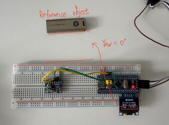
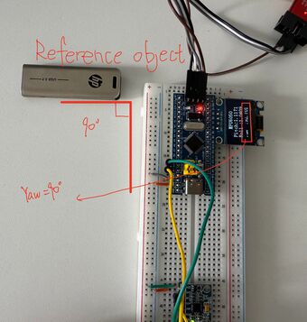
Yaw Rotation
Since our yaw angle is calculated by integrating the Z-axis angular velocity, it is expected to drift over time. However, for short-term motion, it could still reflect relative rotation. We rotated the device on a flat surface and observed the change.
The yaw angle changed appropriately during rotation. However, due to the lack of a magnetometer, long-term drift is still present and was not corrected in our system.
Summary
The table below summarizes the approximate angles observed during different manual movements. The "Reference" column represents rough estimates of the sensor orientation based on intuition and relative movement, not exact measured angles.
| Test Condition | Estimated Tilt | Measured Angle (OLED) | Observation |
|---|---|---|---|
| Flat (Initial) | ≈ 0° | 0° ± 1° | Stable near zero |
| Pitch Forward | ~ +45° | +46° | Correct trend |
| Pitch Backward | ~ -45° | -46° | Correct trend |
| Roll Right | ~ +45° | +46° | Correct trend |
| Roll Left | ~ -45° | -48° | Correct trend |
| Yaw No Rotation | ~ 0° | 0° | As expected |
| Yaw Rotated Clockwise | ~ +90° | +91° | Matches rotation |
Note: The reference angles were estimated by eye during manual movement. No precise angle measurement tools were used.
Pitch and roll estimation was stable and consistent throughout the tests. The angle values responded smoothly to manual tilting and aligned well with expected trends within an approximate ±45° range.
Yaw angle changes were visible and directionally accurate during short-term rotation, but drifted over time due to the lack of a magnetometer for correction.
All three angles were displayed clearly on the OLED screen and updated in real time at approximately 100 Hz.
Overall, the complementary filter worked effectively for basic attitude estimation using only the MPU6050 sensor, especially for roll and pitch. The system demonstrates reliable performance for short-term orientation tracking without external reference.
Discussion
Accuracy and Stability of Roll and Pitch
The complementary filter worked well in estimating roll and pitch angles. These two values stayed stable when the sensor was stationary, and responded predictably when the module was manually tilted. The accelerometer provides a consistent long-term reference by measuring gravity, while the gyroscope enhances short-term responsiveness due to its ability to capture quick changes in angular velocity. Minor fluctuations (within ±1°) were observed, likely caused by hand tremors or ambient vibrations, but overall the performance was satisfactory for basic real-time tracking.
Yaw Angle Limitations
Yaw angle is significantly more difficult to estimate. Unlike pitch and roll, which rely on the gravity vector, yaw involves rotation around the vertical (Z) axis, and cannot be observed by the accelerometer. In this project, yaw was estimated by integrating the gyroscope’s Z-axis angular velocity. While this method works for short-term orientation changes, it introduces drift over time because small sensor biases accumulate with each integration step. Without a magnetometer (e.g., to detect Earth's magnetic field), yaw estimation lacks an absolute reference, making it unreliable in the long term.
Display and Refresh Rate
The OLED screen displays the estimated angles in real time at roughly 100 Hz. This update rate was sufficient to observe smooth changes during hand-held motion. However, due to the limited resolution and refresh speed of the OLED, rapid or subtle angle changes may not be visually apparent. For more precise analysis, data could be logged via serial communication and plotted on a PC.
Potential Improvements
Several enhancements could improve the accuracy and expand the capabilities of this system:
- Adding a magnetometer (e.g., HMC5883L) to correct yaw drift and provide an absolute heading.
- Implementing a more advanced fusion algorithm such as a Kalman filter or Madgwick filter for better dynamic performance.
- Including a calibration routine at startup to correct sensor biases and scaling errors.
- Sending angle data to a PC or mobile device over serial or Bluetooth for richer visualization and analysis.
These changes would bring the system closer to what is used in real-world IMU applications, especially in drones and robotics.
Applications and Extensions
Although this is a small-scale project, the techniques used here reflect real principles behind many motion-sensing systems. Possible applications include:
- Orientation feedback in drones or quadcopters
- Balancing control in two-wheeled robots
- Gesture recognition in wearable or handheld devices
- Head tracking in VR or AR environments
By building this system from scratch—including raw register access, filtering, and angle estimation—we’ve gained a practical understanding of how physical motion is sensed and processed in embedded systems. This hands-on experience ties directly into the themes of the Physics of Sensors course.
References
- [1] MPU6050 Register Map and Datasheet, InvenSense.
https://invensense.tdk.com/products/motion-tracking/6-axis/mpu-6050/
- [2] STM32F103C8T6 Datasheet, STMicroelectronics.
https://www.st.com/en/microcontrollers-microprocessors/stm32f103c8.html
- [3] How to Interface the MPU6050 (GY-521) with STM32, Controllerstech.
https://controllerstech.com/how-to-interface-mpu6050-gy-521-with-stm32/
- [4] STM32 I2C for MPU6050 (e.g., GY-521) Get Angle, GitHub Repository by creative-apple.
https://github.com/creative-apple/STM32_MPU6050_ComplementartFilter
