Temperature and humidity sensors: Difference between revisions
| Line 34: | Line 34: | ||
Connect the 9V battery to the Arduino power socket via the battery clip. | Connect the 9V battery to the Arduino power socket via the battery clip. | ||
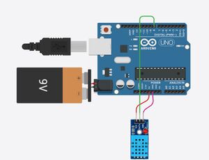
[[File: | [[File:Circuit-diagram.jpg|300px|frameless|center|DHT11 sensor circuit diagram]] | ||
===Programming and Uploading Code=== | ===Programming and Uploading Code=== | ||
Revision as of 16:48, 29 March 2025
Team Member
Chen Andi、Chen Miaoge、Chen Yingnan、Fang Ye
Background
With the advancement of smart home systems, agricultural monitoring, and industrial environmental control, real-time monitoring of ambient temperature and humidity has become increasingly important. Variations in temperature and humidity significantly impact human daily activities, industrial production, and the storage conditions of various products. Traditional temperature and humidity measurement instruments are often expensive or lack real-time data display capabilities. Therefore, designing a low-cost, real-time temperature and humidity monitoring system based on the DHT11 sensor and Arduino holds significant practical and educational value.
Objective
The objective of this project is to design and implement a real-time temperature and humidity monitoring system based on Arduino and the DHT11 sensor, capable of continuously acquiring environmental temperature and humidity data and displaying the results on an LCD1602 screen in an intuitive manner. The system is designed to fulfill the following functions:
- Real-time Data Acquisition: Accurately measures the current ambient temperature and humidity.
- Dynamic Data Display: Continuously updates the LCD screen to reflect the latest measurement data.
- Low Cost and High Scalability: Suitable for various applications such as smart home systems, agriculture, and warehouse environments, with potential extensions to wireless data transmission and other advanced functionalities.
Theory
Equipment Required
- DHT11
- Electronic display
- Arduino
- DuPont Line
- battery-9V
Experiment Steps
Circuit Connection
1.DHT11 Connection
- VCC → 5V (Arduino)
- GND → GND (Arduino)
- Data Pin → Digital Pin
2.Display Connection
- VCC → 5V (Arduino)
- GND → GND (Arduino)
- SDA → A4 (Arduino UNO)
- SCL → A5 (Arduino UNO)
3.Power Connection Connect the 9V battery to the Arduino power socket via the battery clip.

Programming and Uploading Code
1.Installing Libraries
- In Arduino IDE, install the DHT Sensor Library by Adafruit and LiquidCrystal_I2C libraries.
2.Writing Code (Code details omitted)
- Include necessary libraries (DHT).
- Define the DHT11 sensor pin and type.
- Initialize the display and the sensor.
- In the loop() function, read temperature and humidity data and output them to the display and serial monitor.
3.Uploading Code
- Connect Arduino to the computer via USB cable.
- Select the correct board model and port.
Experiment Operation
Disconnect USB Power and Connect 9V Battery.
Observe Temperature and Humidity Data on the Display and Serial Monitor.
Data Analysis
References
BU Y, LUO X, CHEN Y. Temperature and Humidity Acquisition System Based on Sensor DHT11[J]. Computer and Modernization, 2013, 1(11): 133.