STM32-Based IMU Attitude Estimation
This project involves using an STM32 microcontroller and an MPU6050 sensor module to measure angular velocity and acceleration. The collected sensor data will be processed to determine the attitude angles (roll, pitch, and yaw) of the system. The project will include sensor calibration, data filtering (e.g., complementary or Kalman filter), and real-time angle computation for accurate motion tracking applications.
Introduction
This project aims to build a simple but functional system that can estimate the orientation (attitude) of an object in real time. We used an STM32F103C8T6 microcontroller together with an MPU6050 sensor, which includes a 3-axis gyroscope and a 3-axis accelerometer.
By collecting data from the sensor and processing it through our own code, we can estimate how the object is tilted—specifically its roll, pitch, and yaw angles. To make the results more stable and accurate, we applied filtering techniques (e.g., complementary filter) to combine acceleration and gyroscope data.
The project mainly involves:
Reading raw sensor data through I2C communication
Calibrating the sensor to reduce offset and noise
Using a filtering algorithm to compute stable angle values
Updating the angles in real time
This kind of system is commonly used in applications like drones, mobile phones, and robot balance systems. Our goal is to understand how such a system works from both a hardware and software perspective by building one from scratch.
Team Members
LI DING
FAN XUTING
Project Overview
The idea of this project is to estimate the orientation (attitude) of an object using sensor data. We used the MPU6050 module, which combines a gyroscope and an accelerometer, to measure how the object is moving and rotating in space. The sensor data is collected using the STM32F103C8T6 microcontroller through I2C communication.
Since the raw data from the sensor is not very stable or accurate by itself, we applied a filtering method (in our case, a complementary filter) to combine the gyroscope and accelerometer readings. This allows us to reduce noise and drift, and get smoother and more reliable angle values over time.
The final goal is to calculate the roll, pitch, and yaw angles of the system in real time. This kind of setup is commonly used in things like self-balancing robots, drones, camera stabilizers, or even mobile phones for detecting screen orientation. Our project is a small-scale version of such systems, built from scratch to better understand how attitude estimation actually works.
Setup
Equipment
Here are the main components used in this project:
STM32F103C8T6 ("Blue Pill") – A versatile microcontroller for controlling the system.
MPU6050 – A 6-axis IMU sensor that includes both a 3-axis accelerometer and a 3-axis gyroscope.
USB to TTL Serial Converter – Used for programming the STM32 and communicating with the serial terminal.
Jumper wires and breadboard – For making connections between the STM32 and MPU6050.
Power supply (3.3V) – Provided by the STM32 or through an external 3.3V regulator.
The MPU6050 module is powered with 3.3V, and it communicates with the STM32 over the I2C bus.
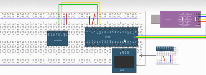
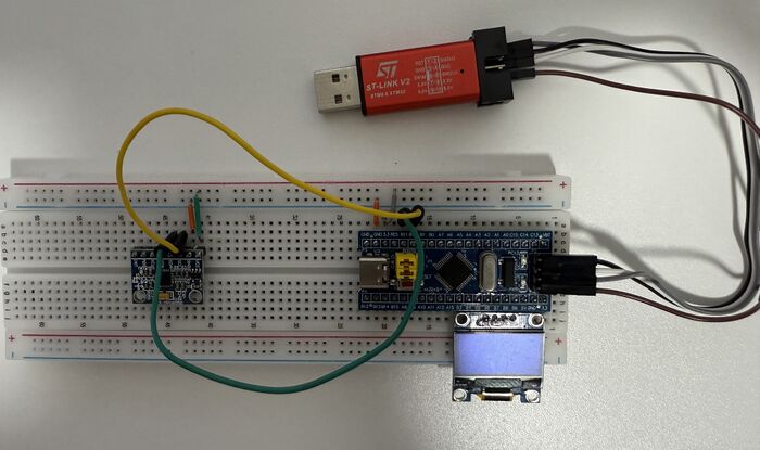
Wiring / Circuit Overview
Here's how the components are connected:
| MPU6050 Pin | STM32 Pin | Notes |
|---|---|---|
| VCC | 3.3V | Powered by STM32 |
| GND | GND | Common ground |
| SDA | PB7 | I2C data line |
| SCL | PB6 | I2C clock line |
The sensor is connected to the STM32 using the I2C interface, which allows the STM32 to read the sensor's data. I2C is a simple and efficient communication protocol for embedded systems.
Optional: A USB to TTL converter is used for programming the STM32 and debugging through the serial port. This allows us to print the sensor data or estimated angles to the terminal.
Software & Code
All the software for this project was written in C, using STM32's standard peripheral libraries. The key steps in the code are:
Initialize I2C communication – This involves setting up the I2C peripheral on the STM32 and ensuring it can communicate with the MPU6050.
Configure the MPU6050 – Setting the sensor’s output scale, enabling the gyroscope and accelerometer, and setting it into the correct mode.
Read raw data – The sensor's data is read from its registers using the I2C bus. This includes accelerometer values (in g) and gyroscope values (in °/s).
Convert raw values – The raw values are converted to physical quantities like acceleration (g) and angular velocity (°/s).
Estimate angles – We use a complementary filter to combine accelerometer and gyroscope data, providing stable roll and pitch angles.
Output results – The final angles are printed via the serial port for easy monitoring.
The code runs in a continuous loop, with updates being sent at a fixed rate (e.g., every 10ms) to ensure smooth, real-time operation.

