Uncategorized files
From pc5271AY2526wiki
Jump to navigationJump to search
Showing below up to 50 results in range #101 to #150.
-
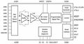 Figure 2 6.jpg 1,344 × 705; 78 KB
-
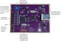 Figure 2 7.jpg 1,524 × 1,023; 144 KB
-
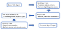 Flowchart.png 1,242 × 614; 41 KB
-
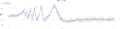 Fringe count plot.png 4,320 × 1,044; 415 KB
-
 Hot-plate.jpeg 1,072 × 1,709; 715 KB
-
 INFineon TLE49681KXTSA1.pdf 1,239 × 1,754, 26 pages; 1.39 MB
-
 Image of the Nanovoltmeter.jpeg 1,600 × 902; 144 KB
-
 Image of the Temperature Difference Measurement.jpeg 1,600 × 900; 150 KB
-
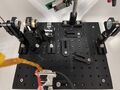 Interferometer expan.jpeg 4,032 × 3,024; 1.97 MB
-
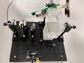 Interferometer photo.jpeg 3,777 × 2,833; 1 MB
-
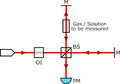 Interferometer setup.png 959 × 722; 34 KB
-
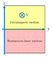 MOKE Diagram EMtheory.png 583 × 659; 30 KB
-
 MOKEgeometries.png 654 × 255; 63 KB
-
 MQ-3.pdf 1,239 × 1,752, 2 pages; 55 KB
-
 Maxwellequations.jpeg 808 × 97; 19 KB
-
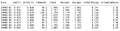 Measured Results (Analyzed).png 1,638 × 426; 160 KB
-
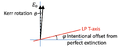 Moke analyzer offset method.png 1,000 × 412; 43 KB
-
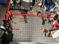 Moke downstream.png 784 × 585; 837 KB
-
 Moke gaussmeter and magnet.png 885 × 663; 1.03 MB
-
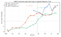 Moke hysteresis loop.png 1,350 × 825; 104 KB
-
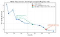 Moke measurement.png 1,200 × 750; 89 KB
-
 Moke sample image.mp4 ; 198 KB
-
 Moke sample image 1.gif 480 × 270; 1.04 MB
-
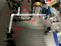 Moke sample image system.png 885 × 661; 811 KB
-
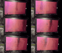 Moke sample imagegif.gif 480 × 270; 1.04 MB
-
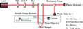 Moke setup.png 961 × 502; 1.84 MB
-
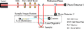 Moke setup2.png 1,150 × 403; 1.77 MB
-
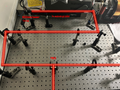 Moke upstream.png 894 × 668; 801 KB
-
 OP07.pdf 1,275 × 1,650, 16 pages; 232 KB
-
 OP27.pdf 1,275 × 1,650, 20 pages; 422 KB
-
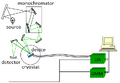 Optical path diagram.png 637 × 443; 43 KB
-
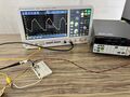 Out-of-room-testing.jpeg 1,707 × 1,280; 267 KB
-
 PARA.png 2,016 × 306; 411 KB
-
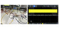 PC5271inductive1.png 1,511 × 755; 803 KB
-
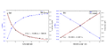 PC5271inductive2.png 1,511 × 755; 185 KB
-
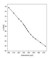 PC5271inductive3.jpeg 1,070 × 1,280; 83 KB
-
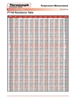 PT100 TABLA R T.pdf 1,239 × 1,754, 2 pages; 63 KB
-
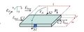 Principle of the Hall effect.jpeg 520 × 198; 20 KB
-
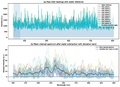 Raw dil.pdf 1,633 × 1,181; 232 KB
-
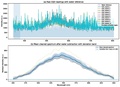 Raw rep.pdf 1,633 × 1,181; 243 KB
-
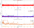 Rest Figure1.png 1,367 × 1,101; 164 KB
-
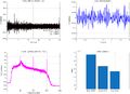 Rest Figure2.png 1,610 × 1,171; 141 KB
-
 Rulerfig.jpeg 1,226 × 914; 129 KB
-
 Rulerfigure.png 1,226 × 914; 1.57 MB
-
 S5971 etc kpin1025e.pdf 1,239 × 1,752, 5 pages; 864 KB
-
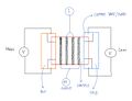 Schematic Diagram of the Experimental setup - Four probe measurement.jpeg 1,280 × 980; 59 KB
-
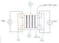 Schematic Diagram of the Two probe measurement.jpeg 1,280 × 948; 59 KB
-
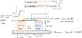 Schematic diagram of the experiment.png 2,161 × 1,000; 519 KB
-
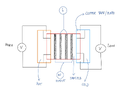 Schematic diagram of the experimental - four probe mesasurement.png 1,280 × 980; 269 KB
-
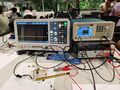 Setup.jpg 972 × 760; 123 KB


