Laser Gyroscope
Some Description
Team members
Darren e0303300@u.nus.edu
Wen Xin e0309271@u.nus.edu
Idea
This project aims to measure some rotation by using the Sagnac effect, by using a loop of fiber as a ring interferometer.
Sagnac effect
When two beams of light are sent into the two ports of a ring interferometer, they travel clockwise (CW) and counter-clockwise (CCW) paths respectively. For a stationary ring interferometer, since the path length traversed by each beam is the same, this leads to interference at the output port.
In the following derivation, we assume the interferometer consist of a singular circular loop. Let's say the interferometer is spinning in the CW direction with rotation rate . Then there will be a change in path length due to the rotation given by
,
where R is the radius of the loop and is the time it takes for the light to travel clockwise or counter clockwise in the loop.
which results in the following
where n is the refractive index of the medium. For ,
As ,
If we use N multiple loops instead of a single loop, substituting ,
Thus, for light of frequency f, we can calculate the Sagnac phase shift:
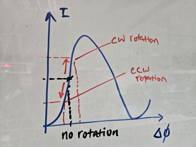
The change in the phase difference between the two paths changes the degree of constructive or destructive interference that happens, resulting in a change in the intensity detected. This is illustrated by the sketch of the graph below. As such, the change in the voltage across the detector corresponds to .
The derivation so far only assumes that we only have 1 polarization of light. However in non-polarizing maintaining fiber, the birefrigence in the fiber causes a change in the polarization of the light when it travels through the fiber, so the resulting light that travels in the CW and CCW direction will in general have different polarizations, resulting in the inability to achieve complete constructive or destructive interference. We will try to ignore effects from polarization first and try to overcome problems with it if necessary.
Parts
50m smf28 fiber spools
20km smf28 fiber spools
2x Thorlabs FGA01FC photodiodes
1550nm Fiber circulator
Fiber paddle
Laser driver
1550nm Laser diode
1550nm Fiber isolator
1st Setup
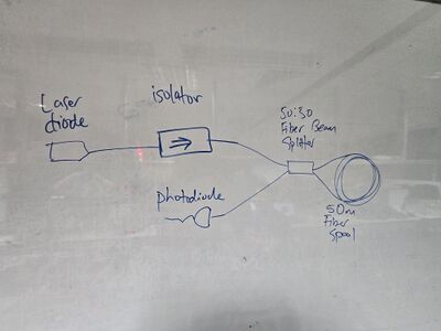
11 and 14 March The main setup will be a fiber based Sagnac interferometer. The setup is as shown below:
Parts used are:
1x laser driver
1x 1550nm DFB laser diode
1x fiber isolator to prevent backreflections to the laser diode
1x 50:50 fiber beam splitter at 1550nm
1x 50m smf28 fiber coil
1x FGA01FC photodiode
a lot of fiber to fiber connectors
1x 1m smf28 fiber for connecting beam splitter to the photodiode
2x apc to pc smf28 fiber
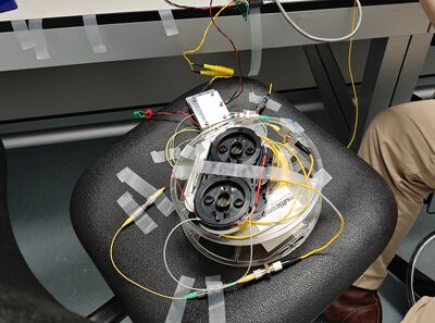
All components are taped to the 50m fiber loop, and the fiber loop is placed on top of a rotating chair. The fiber loop as a diameter of ~10cm. The interferometer output is sent to a photodiode, which is read out as a voltage reading on an oscilloscope.
When initially testing our 1st iteration, rotating the 50m fiber coil caused a change in the voltage output of the photodiode. However, the change in the voltage output remained even after the fiber coil is stationary, which should not happen since any voltage changes due to the Sagnac effect should only come from movement, and should not depend on the final orientation.
To further investigate, we removed the fiber loop and connected only the 2 ends of the fiber beam splitter together. In practice, rotating this setup should show a very small change or no change since the area enclosed by the fiber is much smaller as compared to the fiber coil. However, we still observe the same voltage change as before. We suspected that the voltage change we observe might be due to birefrigence in the fiber instead. When fiddling with various fibers in the setup, similar voltage changes were observed as well. So the voltage change is likely due to the polarization change when the fiber was moving instead, which caused a change in the intensity of the interferometer output.
Attempting to fix this issue, all stray fibers were taped down to prevent them moving and changing the polarization of the light, but this did not seem to work.
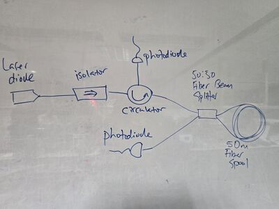
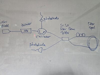
Plan to investigate this further using a circulator and another photodiode to convert the Sagnac configuration into a Mach-Zehnder configuration, and look at the output of both ports.
2nd setup
18 March
We moved all the components to a small optical breadboard, except for the laser diode and the photodetector. All fibers are taped down to the breadboard with only 2 fibers untaped: one from the 1550nm laser diode to the setup, and one from the setup leading to the photodetector. With this new setup, we seem to get the expected behaviour? A voltage change from the photodiode is only observed when the fiber coil is moving and returns to its original value when its stationary. So with this setup, it seems we minimized the amount of unwanted polarization change in the fiber that occurs when we rotate the chair.
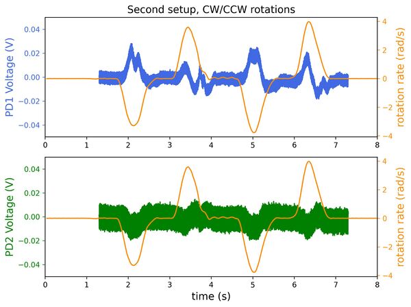
In order to verify the rotation rate of the fiber coil, we placed a phone with a gyroscope readout enabled (phyphox). We then turn the chair clockwise and counter-clockwise continuously, and plot the results below:
The orange trace represents the output from the phone's gyroscope, while the blue trace and green trace represents the voltage readings from PD1 (connected to the 50:50 beam splitter) and PD2 (connected to the circulator) respectively. Clearly, we do observe correlation between when the chair is rotated, and when fluctuations in the PD voltage outputs are observed. We also see that the fluctuations from PD1 and PD2 are anti-correlated, which verifies the observation of interference.
However, there are clearly several issues from this measurement. First, we observe much greater noise, and much lower sensitivity from PD2's output. We suspect that the circulator might be the cause of this. Given that, we will mainly be looking at the PD1 voltage readings. Second, we expect the voltage signal to change one way when the chair is rotated CW, and to change the other way when the chair is rotated CCW. The plot of PD1 voltage above shows that when the rotation rate is negative (CW), the voltage change is positive, whereas when is negative (CCW), the voltage change can be both positive or negative. We suspect that this might be due to the operating point being close to a minima in the interference pattern (the sketch in the idea section), and that the CCW rotation is sufficient to push the signal over the minima.
We also observe fluctuations at the peaks of the rotation rate when , which does not agree with the relatively smooth rotations as indicated by the phone gyroscope readings.
Third setup
The results from the previous setup seems to indicate some improvements can still be made. The first improvement is to include a polarization paddle at one side of the fiber coil, which should allow us to tune the polarization of the light interfering at the 50:50 BS to some extent. We also noticed that the fiber from the laser source to the isolator was hanging, and lightly disturbing this fiber led to small but visible fluctuations in the PD readings. So we squeezed the laser source onto the chair (this seemed to be the cause of the fluctuations discussed at the end of the previous section).
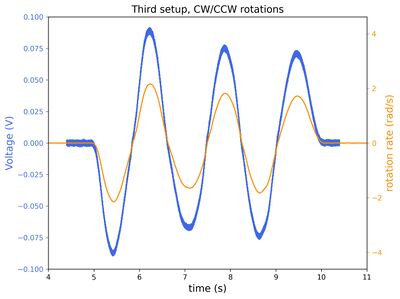
For our first measurement, we adjusted the polarization in the interferometer such that the voltage reading the photodiode is midway between the maximum and minimum voltage. With just this change, we already see a large improvement compared to the second iteration. We can clearly correlate both CW and CCW rotations.
Next, we would like to verify our claim during our second iteration that we are at the minima or maxima of the interference pattern, causing rotations in either direction to create the same voltage change. This was done by adjusting the polarization till the voltage of the photodiode was at its minimum or maximum. In both cases, we see that both CW and CCW rotations causes either only a positive or negative change in voltage, verifying our claim. The difference in voltage change for CW and CCW rotations can be attributed to how far away we are from actual maximum or minimum voltage.
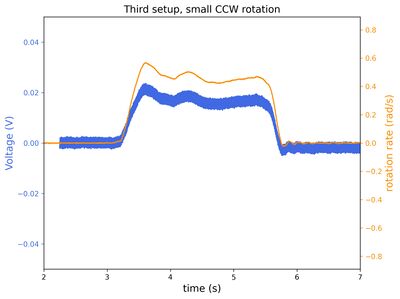
With a slow CCW rotation, we can see in the plot below, that our setup can observe rotations on the order of 0.1 rad/s or 5.7 deg/s.
Lastly, we would like to quantitatively infer how sensitive our laser gyroscope is. Sensitivity is defined as the smallest rotation rate that can be detected by our gyroscope setup. To measure this, first we correlate the peak measurements from the laser gyroscope and the phone gyroscope in the first "CW/CCW" plot, and estimate a conversion factor of 42.2(2) mV/rad/s (assuming we remained in the linear range). We then calculate the root-mean-square voltage fluctuations of the laser gyroscope readings at zero rotation, at = 1.26 mV. Therefore, we estimate that our setup is limited to measuring > 0.03 rad/s, or 1.7 deg/s rotations.
Fourth Setup
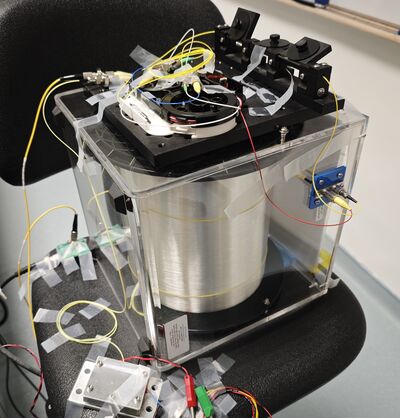
Since we have a 20km fiber spool lying around, we decided to replace the 50m fiber spool with the 20km fiber spool, with a spool diameter of ~15cm.
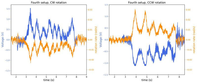
As expected, we see that the 20km fiber spool laser gyroscope is much more sensitive to rotations, where it is clearly sensitive to rotation rates well below 0.01rad/s. In theory, from the larger spool radius and the longer fiber length, we expect a ~600 times increase in the phase shift sensitivity.
Again, we correlate the peak measurements from the laser gyroscope and the phone gyroscope in the "CW" plot (not the "CCW" plot, as it seems like the laser gyroscope readout plateaued at several points), and estimate a conversion factor of 60(4) V/rad/s (again assuming we remained in the linear range). With rms voltage fluctuations of = 54.6 mV at zero rotation, we estimate that with the 20 km fiber spool, our setup is limited to measuring > 0.0009 rad/s, or 0.05 deg/s rotations.
We suspect that the lower-than-expected increase in sensitivity is due to a high noise floor. While there are various factors such as detector noise, we think that the most significant factor might be environmental noise affecting the fiber spool. Going from a cladded 50m fiber spool to a uncladded 20 km spool, the laser gyroscope is sensitive enough that we observe fluctuations in the laser gyroscope voltage that coincides with conversations in the other side of the room.
Conclusion
In summary, we managed to construct a fiber-optic laser gyroscope that can clearly differentiate between CW and CCW rotations, and also different rotation rates. We also observed an increase in sensitivity when using a longer fiber spool, albeit limited by high noise floor which prevented us from reaching the expected ~600 times increase in sensitivity.
For possible improvements, the first would probably be to isolate the 20 km fiber spool from external sources of noise, for example coating the walls of the container with rockwool. Another improvement would be to construct a platform that spins using an electric motor, so that we can reliably keep the rotation rate constant. Beyond that, other possible measurements include measuring the long-term stability of the gyroscope, such that we can evaluate the Allan deviation of the gyroscope.
