Magnetic field sensing using a fluxgate magnetometer
Introduction to magnetic field sensing
Magnetic field sensing plays a crucial role in both scientific research and practical applications, ranging from searching for fundamental physics, geophysical nagigations, to industrial and biomedical uses. Magnetic sensors are used to detect, map, and measure the intensity and direction of magnetic fields. There are several methods for sensing magnetic fields, and the choice of sensor depends on the application requirements, such as sensitivity, bandwidth, and environmental robustness.
Different types of magnetometers
- Fluxgate magnetometers use ferromagnetic cores and detect magnetic fields by sensing nonlinear changes in core permeability [1]. They are valued for their robustness and precision in low-field measurements, making them ideal for space missions and geological studies.
- SQUID magnetometers (Superconducting Quantum Interference Devices) are among the most sensitive magnetic field detectors. Operating at cryogenic temperatures, SQUIDs exploit quantum interference in superconducting loops to detect fields as small as femtoteslas. They are widely used in biomagnetism (e.g., MEG – magnetoencephalography) and in fundamental physics experiments.
- Optically pumped magnetometers rely on the interaction between light and spin-polarized atoms, typically alkali metals like rubidium or cesium [2]. These sensors can achieve extreme sensitivity while operating at room temperature. The most sensitive optical magnetometers, such as spin-exchange relaxation-free (SERF) devices, can reach sensitivities below 1 fT/√Hz [3]. More compact or portable designs, while less sensitive, still operate effectively in the picotesla to nanotesla range, making them attractive for biomedical, navigation, and remote sensing applications.
- Hall effect sensors are solid-state devices that measure the voltage generated by a magnetic field perpendicular to an electric current. They are simple, low-cost, and widely used in consumer electronics and industrial systems where high sensitivity is not critical.
- Magnetoresistive sensors (AMR, GMR, TMR) rely on changes in resistance due to the presence of a magnetic field. They offer high bandwidth and miniaturization potential, which are useful in automotive and robotics applications.
Each of these technologies offers a unique combination of sensitivity, size, cost, and operational constraints.
Applications
Magnetic sensors find applications across a wide spectrum of fields:
- In fundamental physics, they are used in searches for exotic particles and precision measurements of fundamental constants [4].
- In geophysics, magnetometers are employed for mineral exploration, archaeology, and mapping Earth's magnetic field.
- In navigation, especially in aerospace and underwater contexts, magnetic sensing provides orientation and heading information where GPS is unavailable [5].
- In the biomedical field, ultra-sensitive magnetometers (e.g., SQUID and optical) enable non-invasive detection of weak magnetic signals from the brain and heart [6].
- In industry, they are used for non-destructive testing, monitoring electric motors, and detecting ferrous materials in quality control.
Modern advances in materials science, quantum optics, and electronics continue to expand the reach and capability of magnetic field sensing technologies.
Operation principles of a fluxgate magnetometer
How does a fluxgate magnetometer work?
A fluxgate magnetometer works by exploiting the magnetic response of a ferromagnetic core to detect an external magnetic field. It detects changes in magnetic permeability due to the presence of an external field, typically producing a signal at 2nd harmonic of the excitation frequency. In a fluxgate sensor, the core material has very high magnetic permeability, meaning the core material can concentrate magnetic fields very well. Besides, it reacts strongly to changes in external fields. Its permeability changes nonlinearly as the material saturates, which is crucial for generating detectable signals (like the 2nd harmonic) when there's an external field.
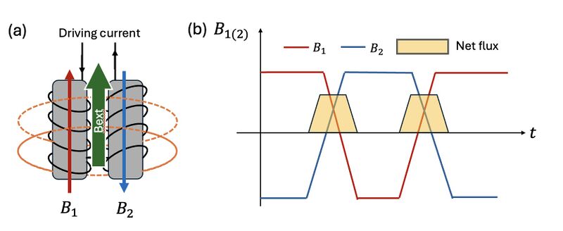
Specifically, as shown in Figure 1, the core of a typical fluxgate magnetometer consists of two identical ferromagnetic rods with magnetic permeability , each wrapped with a coil through which an alternating driving current flows in opposite directions. This setup generates magnetic fields and that are also in opposite directions, where and are auxiliary magnetic field generated by the coils. These coils are driven by a time-varying current (Figure 1b), typically a square wave. A secondary (sensing) coil is placed around both of the two cores to detect changes in net magnetic flux. In the absence of an external magnetic field, the opposing magnetizations and cancel out exactly, resulting in zero net magnetic flux through the sensing coil. Therefore, no voltage is induced in the sensing coil.

However, when an external magnetic field is applied along the axis of the cores, it breaks the symmetry between the two magnetic responses (Figure 2b). This results in the emergence of non-zero total magnetic flux through the sensing coil. According to Faraday's Law of Induction and Lenz's Law, a time-varying magnetic flux through the coil induces an electromotive force (EMF) . As Figure 2b shows, the net flux induced voltage typically appears at twice the driving frequency and forms the output signal of the magnetometer, allowing detection of the external magnetic field.
Manual of the 'Magnetic Field Sensor FLC 100' used in the experiment
The FLC 100 magnetic field sensor was used in this experiment. The magnetic sensor has a compact design, high sensitivity, and low noise characteristics, making it well-suited for measuring weak magnetic fields in a laboratory setting. The working parameters of the sensor are listed below:
| Parameter | Value |
|---|---|
| Measurement range | ±100 µT |
| Output voltage | ±1 V per 50 µT (max ±2.5 V) |
| Reference output | 2.5 V with respect to ground (OUT−) |
| Output impedance | <1 Ω |
| Load conditions | >1 kΩ resistance, <100 pF capacitance |
| Bandwidth | DC to 1 kHz (−3 dB) |
| Noise | <0.5 nT RMS (0.1–10 Hz), ~150 pT/√Hz at 1 Hz |
| Zero drift | <2 nT/K |
| Supply voltage | 5 V ±5% |
| Supply current | ~2 mA |
| Operating temperature | −40 °C to +85 °C |
| Dimensions | 44.5 mm × 14 mm × 5.5 mm |
| Detection coil length | 22 mm |
Source: Stefan Mayer Instruments – FLC 100 Datasheet
Experiment
Setup of the experiment
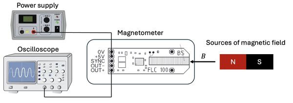
In this experiment, a power supply provides a 5 V driving voltage for the fluxgate magnetometer (FLC100). The output signal from the magnetometer is monitored using an oscilloscope. A schematic of the experimental setup is shown below.
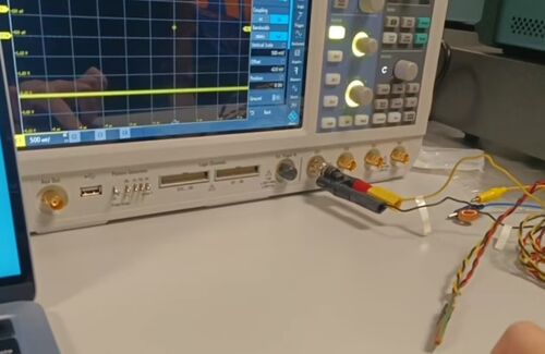
To demonstrate the basic operation of the magnetometer, a permanent magnet is used as a test source. As the magnet is moved in proximity to the sensor, changes in the output voltage are clearly observed, indicating a varying magnetic field, as the video below shows:
For calibration purposes, in the following experiments, both a permanent magnet and a current-carrying coil are used. These sources allow characterization of the magnetometer's response under controlled magnetic field conditions.
Modeling and measurement of a permanent magnet
Firstly, a disk-shaped permanent magnet is used as the source of the magnetic field. The magnetic field distribution around the magnet is simulated using COMSOL Multiphysics, modeling the magnet as a disk with a diameter of 1.9 cm and a thickness of 3 mm. A stream plot of the three magnetic field components is shown in Figure 4(a). It is important to note that the magnetometer measures only the scalar component of the magnetic field, in our case, the is projected along the axis of the magnetometer. The component is evaluated along the blue cutline indicated in Figure 4(a), where it is observed to be very small—on the order of microtesla—because the magnetic field is predominantly out-of-plane near the disk.
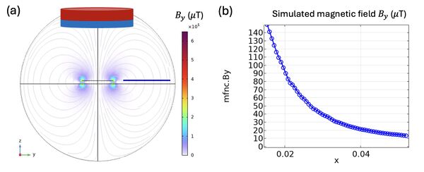
To experimentally validate the simulation results, we position the magnet adjacent to a fluxgate magnetometer and measure the magnetic field strength as a function of distance (Figure 5a). The measurements are repeated three times to ensure reproducibility. The measured voltages and the corresponding calculated magnetic field strengths are presented in Figures 5b and 5c, respectively.
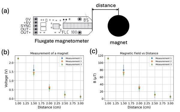
As expected, the magnetic field strength decreases with increasing distance from the magnet, following an approximate inverse relationship. The repeated measurements exhibit small variations, indicating good measurement consistency and reliability of the setup. Discrepancies between the experimental data and the simulation may be attributed to factors such as misalignments in positioning, imperfections in the magnet’s shape or magnetization, and environmental magnetic noise.
Modeling and measurement of a toroidal solenoid
In this section, we present the modeling and experimental measurement of the magnetic field generated by a current-carrying coil.
The coil used in the experiment is a toroidal solenoid, as illustrated in Figure 6. A toroidal solenoid consists of a wire wound into a circular loop, forming a torus-shaped structure. The toroid used in this experiment has an inner radius of approximately , an outer radius of approximately , and a total number of turns .
One important characteristic of a toroidal solenoid is that its magnetic field is largely confined within the core of the toroid, with negligible field outside under ideal conditions. The magnetic field inside the toroid is theoretically given by [7]:
where is the current through the coil. As shown in Figure 6(b), the magnetic field inside the toroid is strong and azimuthally symmetric, while outside the toroid, it ideally vanishes.
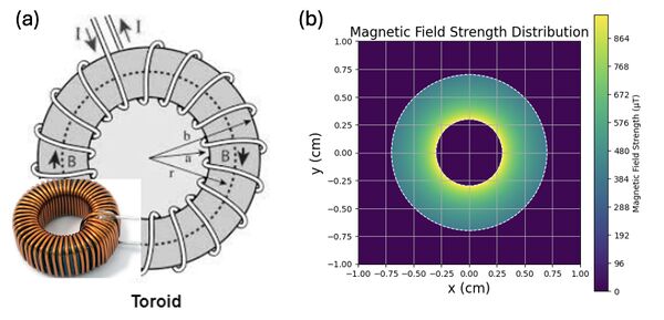
Due to the finite size of the magnetometer probe, we were only able to measure the magnetic field outside the toroid. Measuring inside the toroid would require a significantly smaller probe to fit within the core without disturbing the field distribution.
Although the ideal toroidal solenoid predicts no magnetic field outside, in practice, a finite external field is observed. This residual magnetic field arises primarily from the finite size of the coil, imperfections in the winding (such as turns that are not perfectly azimuthal or uniformly spaced), and edge effects at the inner and outer boundaries of the toroid.
At distances much larger than the toroid's dimensions, the external magnetic field behaves similarly to that of a magnetic dipole and decays approximately as . In our measurements, by varying both the current amplitude and the distance from the toroid, the magnetic field was found to follow this trend, as shown in Figure 7.
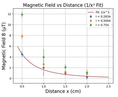
To quantitatively describe the decay behavior, we fit the data to a model of the form:
where is a proportionality constant that depends on the current, and accounts for geometric offsets such as probe size or alignment errors. The fitting results show good agreement with the expected dipole behavior, and the linear dependence of on current further supports the consistency with the Biot–Savart law.
In conclusion, the experimental observations confirm that at distances large compared to the toroid’s dimensions, the magnetic field outside the toroidal solenoid decays as and scales linearly with the current, consistent with dipole field behavior due to practical imperfections.
Discussions
Possible Improvements to Measurement Accuracy
1. Improved Alignment of Experimental Setup
As observed in the experiment, slight misalignments between the magnet and the fluxgate sensor could contribute to discrepancies between the experimental measurements and the simulation results, particularly when measuring the magnetic field distribution around the disk magnet. To improve measurement accuracy, better alignment methods, such as automated positioning systems could be utilized.
2. Use of Alternative Controllable Magnetic Sources
While a permanent magnet and a toroidal solenoid were used to demonstrate the fluxgate magnetometer's functionality, exploring other controllable magnetic sources could offer further advantages in calibration and measurement accuracy. For example, Helmholtz coils could generate highly uniform and adjustable magnetic fields, enabling more precise control over the field strengths.
3. Suppression of Magnetic Noise
Environmental magnetic noise and sensor-induced noise are significant contributors to the variability in the measurements. To reduce the effects of magnetic noise, incorporating magnetic shielding could provide a more stable magnetic environment. In addition, implementing active noise cancellation techniques or low-pass filters could help suppress high-frequency noise that may affect the sensor's performance. These improvements would help achieve more reliable data by minimizing unwanted interference from external magnetic fields.
Analysis of noise
1. Environmental Magnetic Noise
The experimental setup exhibited small variations in the measurements, which can be attributed to environmental magnetic noise. Magnetic fields from nearby electronic devices, power lines, or even the Earth's geomagnetic field could interfere with the sensor’s readings. A potential solution to minimize these effects is to conduct the experiments in a magnetically shielded environment. Additionally, enhancing the sensor's ability to distinguish between external noise and the magnetic signal of interest would improve measurement accuracy. This could be achieved through software-based filtering techniques or hardware modifications to the sensor design, which would help isolate the desired signal more effectively.
2. Intrinsic Sensor Noise
Intrinsic noise from the fluxgate sensor, such as thermal noise or electronic noise in the circuitry, may also contribute to measurement uncertainty. The FLC 100 sensor has a specified noise level of 150 pT/√Hz, which is significantly lower than the measured magnetic field and therefore does not serve as the primary source of noise. Nevertheless, operating the sensor in a low-temperature environment could help suppress thermal noise from the electronics, potentially further reducing the overall noise contribution.
3. Vibrations of the Experimental Setup
Vibrations in the experimental setup, whether originating from the laboratory environment or the sensor itself, could lead to fluctuations in the measured signal. These vibrations might alter the position or orientation of the magnet or sensor, introducing noise in the output signal. To mitigate this, vibration isolation techniques, such as placing the sensor on an optical table with active vibration damping, could be employed. Furthermore, improving the mechanical stability of the mounting system would ensure that the sensor remains stationary during measurements, minimizing noise caused by positional shifts.
References
[1] Primdahl, F. (1979). The fluxgate magnetometer. Journal of Physics E: Scientific Instruments, 12(4), 241.
[2] Budker, D., Romalis, M. Optical magnetometry. Nature Phys 3, 227–234 (2007).
[3] Kominis, I. K., Kornack, T. W., Allred, J. C., & Romalis, M. V. (2003). A subfemtotesla multichannel atomic magnetometer. Nature, 422(6932), 596-599.
[4] Bass, S. D., & Doser, M. (2024). Quantum sensing for particle physics. Nature Reviews Physics, 6(5), 329-339.
[5] Caruso, M. J. (1997). Applications of magnetoresistive sensors in navigation systems (No. 970602). SAE Technical Paper.
[6] Aslam, N., Zhou, H., Urbach, E. K., Turner, M. J., Walsworth, R. L., Lukin, M. D., & Park, H. (2023). Quantum sensors for biomedical applications. Nature Reviews Physics, 5(3), 157-169.
[7] Griffiths, D. J. (2023). Introduction to electrodynamics. Cambridge University Press.