Motor-driven Rotary Plate Speed Measurement via the Hall Effect Sensor
This project utilizes a Hall effect sensor to measure the rotation speed of a circuit board-driven rotary plate through magnetic field variation detection.
Introduction
The precise measurement of motor rotation speed holds great importance across scientific research, industrial automation, automotive electronics, and energy technologies. Utilizing the Hall effect, a phenomenon where a conductor moving through an orthogonal magnetic field generates a measurable voltage, Hall effect sensors have been regarded as a dominant solution for rotation speed detection due to their non-contact operation, exceptional reliability, and cost-effectiveness.
This study systematically investigates a turntable rotation speed measurement system utilizing Hall effect sensor technology, with a general discussion of theoretical principles, hardware implementation, and experimental validation.
Sensor Working Principle
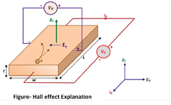
Hall Effect
When an electric current flows through a conductor and a magnetic field is applied perpendicular to the direction of the electric current with intensity , a transverse Hall voltage will be generated across the lateral surfaces of the conductor.
Hall Effect Sensor
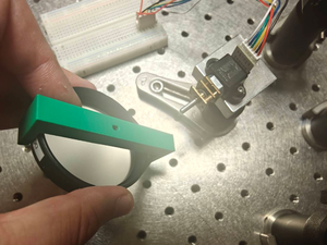
In the Hall Effect sensing system, magnets are uniformly mounted on the periphery of the motor shaft, while a Hall effect sensor is fixed adjacent to this shaft. When a magnet approaches the sensor during shaft rotation, the Hall sensor generates a digital pulse signal (switching between high and low voltage levels).
The rotation speed is calculated by measuring the number of pulses per unit time, with the fundamental relationship expressed as:
Motor Implementation
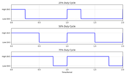
DC Motor with PWM Voltage Supply
For rotation speed regulation of the DC motor, we implemented Pulse Width Modulation (PWM) via the microcontroller's programmable output. By adjusting the PWM duty cycle parameter (0-255), the effective input voltage to the motor is controlled through the modulation of high-level pulse duration. This relationship is mathematically expressed as:
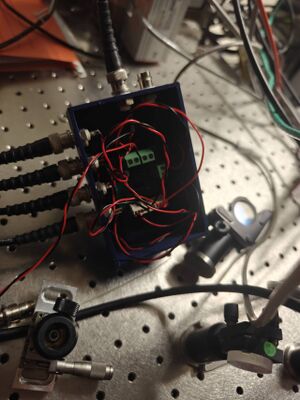
Rotary Plate with Gear System
The DC motor, powered by this modulated voltage , drives the rotary plate through a gear transmission system. Considering the combined effects of gear reduction ratio and circuit internal resistance , the rotary plate's rotational speed exhibits the following proportional relationship with modulated voltage expressed as:
where is motor velocity constant.
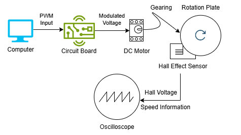
Controlling System Process of Rotation Motor with Hall Effect Sensor
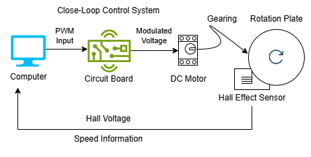
The diagram below illustrates the working process of the motor system. The central control system inputs PWM parameters into the circuit board, which regulates the PWM voltage supplied to the motor. The motor drives the rotary plate and thereby activates the Hall effect sensor, which outputs Hall voltage pulses containing speed information to the oscilloscope.
Data Measurement and Analysis
Data Measurement
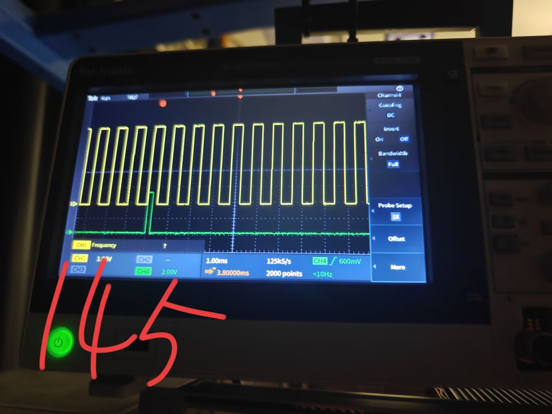
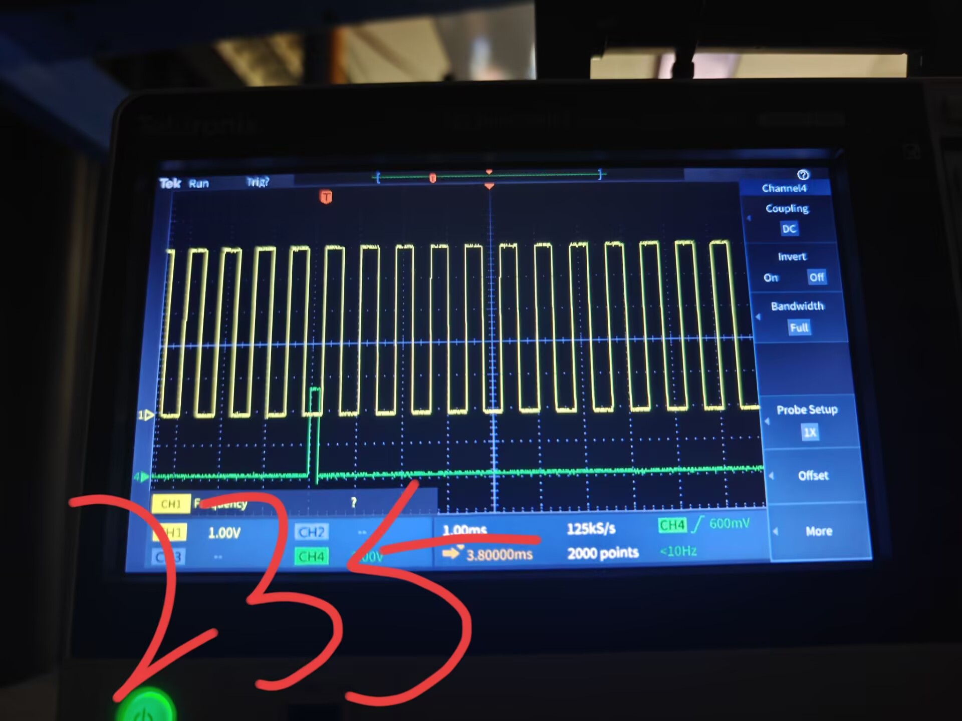
With given PWM Values from 105-255, the rotation speed was measured 5 times per 10-unit PWM increase with the Hall Sensor. For validation, we also applied Laser Tachometer to measure the real rotation speed of the rotary plate. The figures below show the measurement of pulses in one sampling duration on the oscilloscope screen.
 |
 |
Data Statistics
The measurement data are listed as the table below.
| PWM Value | 105 | 115 | 125 | 135 | 145 | 155 | 165 | 175 | 185 | 195 | 205 | 215 | 225 | 235 | 245 | 255 |
|---|---|---|---|---|---|---|---|---|---|---|---|---|---|---|---|---|
| Hall Sensor Measurement /RPM | 203.246 | 208.344 | 214.442 | 226.222 | 235.174 | 242.979 | 247.954 | 249.613 | 251.271 | 257.906 | 259.564 | 266.199 | 268.686 | 276.150 | 279.467 | 284.711 |
| Tachometer Measurement /RPM | 204.8 | 212.5 | 219.0 | 224.5 | 231.6 | 237.6 | 243.6 | 247.6 | 252.7 | 256.0 | 262.2 | 267.0 | 272.6 | 278.1 | 282.2 | 286.8 |
| Relative Error | 0.8% | 1.9% | 2.1% | 0.8% | 1.5% | 2.3% | 1.8% | 0.8% | 0.6% | 0.7% | 1.0% | 0.3% | 1.4% | 0.7% | 1.0% | 0.7% |
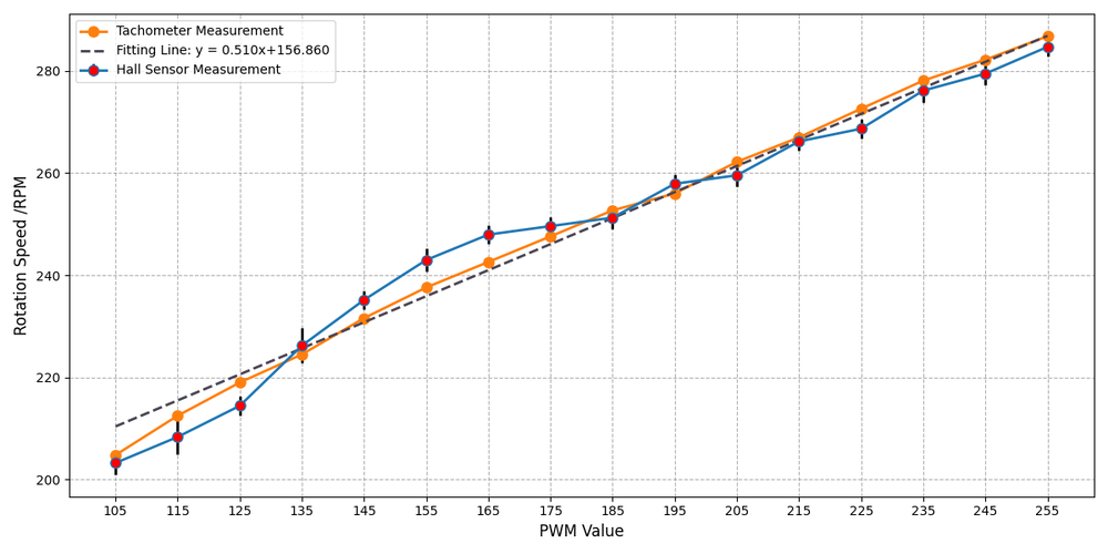
We also plotted the measurement data with a linear regression line (R² = 0.969) as below.
Data Analysis
The measurement demonstrated that the rotation speed measured by the Hall effect sensor exhibits a low relative error (<2%) compared to the ground-truth values obtained from a laser tachometer, thereby validating the accuracy of this methodology.
Furthermore, a linear regression analysis of rotation speed versus PWM values confirmed the strong linear correlation between rotary plate's speed and supply voltage (R² > 0.95). This result further substantiates the feasibility of Hall effect sensors for reliable speed measurement across varying rotation speed.
Additionally, the relative errors observed in the experimental results primarily stem from the following limitations: low temporal accuracy of the voltage oscilloscope, large standard deviation of the measured data.
Conclusion & Outlook
In this study, we developed a circuit board-based control platform with PWM-driven voltage modulation to regulate rotary plate's rotation speed, and conducted experiments to evaluate the Hall effect sensor's speed measurement performance. The results demonstrate that the Hall sensor achieves high measurement accuracy (relative error <2%). In contrast to handheld laser tachometers requiring precise optical alignment, the Hall effect solution offers three distinct advantages: integrated structure for setup, non-contact measurement capability, and cost-effectiveness. This approach enables reliable broad-range speed monitoring and provides a streamlined methodology for laboratory-scale rotational speed measurement applications.
Building upon the experimental limitations identified, we propose the following directions for future research to advance the system's capabilities:
1. Broader range of rotational speed measurements. In our experiments, rotation speeds were limited to 200-300 rpm due to motor working voltage constraints and the rotational resistance of the rotary plate linkage. Expanding the range of speed measurements will help clarify the application occasions for Hall effect sensors and prevent errors caused by Hall voltage relaxation in the sensor's output under extremely high rotation speeds.
2. Physical modeling of plate rotation. By comparing theoretical parameters with real-world laboratory measurements, we aim to establish a more precise speed-voltage dependency relationship. This will enable better evaluation of the accuracy of Hall effect measurement results across different rotational speeds.
3. Closed-loop control of rotation speed. By feeding back real-time rotation speed information to the central control system, the PWM values can be dynamically adjusted based on instantaneous speed detections. This closed-loop approach ensures stable and consistent output of the rotary plate's rotation speed.
Appendix: Arduino Code for circuit board
<syntaxhighlight lang="arduino">
#include <PWM.h> int motor_pinENABLE = 3; int pin_trigger = 8; int speed = 0; String from_python; int frequency = 1000;
void setup() {
 // put your setup code here, to run once:
 InitTimersSafe();  //sets the frequency for the specified pin
 bool success = SetPinFrequencySafe(motor_pinENABLE, frequency);
 //if the pin frequency was set successfully, turn pin 13 on
 if(success) {
   pinMode(motor_pinENABLE, OUTPUT);
   digitalWrite(motor_pinENABLE, LOW);
 }
 Serial.begin(9600);
 Serial.setTimeout(10);
 pinMode(pin_trigger, OUTPUT);
 digitalWrite(pin_trigger, LOW);
}
void loop() {
 // put your main code here, to run repeatedly:
 if (Serial.available()) {
   from_python = Serial.readString();
   Serial.flush();
   speed = from_python.substring(0,3).toInt();
   if (speed > 50){
   pwmWrite(motor_pinENABLE, 50);// from 1 to 255
   delay(100);//ms
   }
   if (speed > 100){
   pwmWrite(motor_pinENABLE, 100);// from 1 to 255
   delay(100);//ms
   }
   if (speed > 150){
   pwmWrite(motor_pinENABLE, 150);// from 1 to 255
   delay(100);//ms
   }
   if (speed > 200){
   pwmWrite(motor_pinENABLE, 200);// from 1 to 255
   delay(100);//ms
   }
   Serial.println(speed);
   pwmWrite(motor_pinENABLE, speed);// from 1 to 255
   delay(1000);//ms
   delay(5);//ms
   digitalWrite(pin_trigger, HIGH);
   delayMicroseconds(400);//us
   digitalWrite(pin_trigger, LOW);
   delay(100);//ms
   pwmWrite(motor_pinENABLE, 0);
 }
 delay(1);
}
</syntaxhighlight>